1. INTRODUCTION
If we enter a dark room, objects present there are not visible. However, if a bulb is switched on, everything in the room becomes visible. It shows that for vision the presence of light is essential.
Definition of Light: It is an invisible energy which causes in us sensation of sight (vision). Since light is obtained from heat energy, i.e., when an object is heated to a temperature beyond [500 0C, we can say that light is a kind of energy].
It must be kept in mind that light energy makes the surrounding objects visible, but by itself it is an invisible energy.
Example: If we are seeing a coloured poster, then we are seeing only the poster and not the coloured lights reflected fronts it. It is because light is invisible. The various colours reflected from the poster excite the retina of the eye, which in turn sends a message to the brain. It is the brain which finally makes out the colours of the poster. Thus, we can conclude that light is an invisible energy which causes in us sensation of vision.
Sources of Light: Sun is the primary source of light for mankind. In addition to it, lighted bulb, a fluorescent tube, a lighted candle ,a kerosene oil lamp, etc., are other sources of light.
Speed of Light: Light travels at very fast speed i.e., m/s. It means the speed of light is 300000000 m/s or 300000 km/s.
Luminous Bodies: The bodies which give out light energy by themselves are called luminous bodies. Examples: The sun, the stars, glow worm etc.
Non-luminous Bodies: The bodies which do not give light energy by themselves , but reflect the light energy falling on them are called non-luminous bodies. Examples: moon, wood, furniture etc.
2. TERMS RELATED TO LIGHT
1. Optical Medium: Any material (or) non-material through which light energy passes wholly (or) partially is called optical medium
Examples: Vaccum, air, water, glass etc.
2. Homogeneous Medium: An optical medium which has a uniform composition throughout is called homogeneous medium.
Examples: Vaccum, diamond, distilled water, pure alcohol etc.
3. Heterogeneous Medium: An optical medium, which has different composition at different points is called heterogeneous medium.
Examples: Air, muddy water, fog, mist, clouds, smoke etc.
4. Transparent Medium: A medium which allows most of the light energy to pass through it is called transparent medium.
Examples: Vaccum , glass, clear air, alcohol, benzene etc.
5. Translucent Medium: A medium which partially allows the light energy to pass through it is called translucent medium.
Examples: oiled paper, tissue paper, ground glass, butter paper etc.
6. Opaque Bodies: The bodies which do not allow the light energy to pass through them are called opaque bodies.
Examples: Bricks, wood, metals etc.
7. Point Source of Light: A source of light which is of the size of pinhead is called point source of light.
Example: The pinhole act as a point source of light.
8. Extended Source of Light: Any source of light which is bigger than point source of light is called extended source of light
Examples: Bulb, Tube light, burning candle etc.
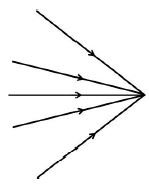
9. Ray of Light: The path along which light energy travels in a given direction is called ray of light.
![]()
10. Beam of Light: A collection of number of rays of light is called beam of light.
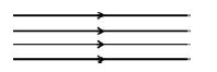
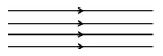
11. Parallel Beam: When the rays of light travels parallel to each other, then the collection of such rays is called parallel beam.
12. Divergent Beam: When the rays of light originating from a point ,travel in various directions, then the collection of such rays is called divergent beam.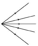
Example: The rays coming out from a bulb or a burning candle or a car headlight constitute a divergent beam.
Note: A point source produces a divergent beam of light.
13. Convergent Beam: When the rays of light coming from different directions, meet at a point then the collection of such rays is called convergent beam.
Example: If a parallel beam is made to pass through a convex lens, then it meets at a point. This kind of collection of rays is called convergent beam of light.
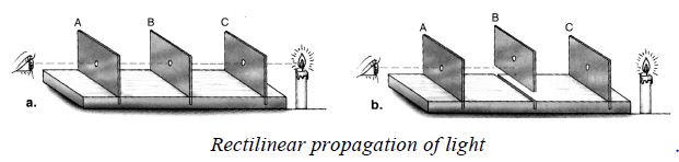
3. RECTILINEAR PROPAGATION OF LIGHT
Light travels in a straight line as long as it is travelling in the same medium. We can observe that light travels in a striate line when we observe the beam of a car headlight on a misty night or a beam of a torchlight entering a smoky room. We can also perform an experiment to demonstrate that light travels in a straight line.
Experiment 1
Aim: to demonstrate that light travels in a straight line
Aids: three square cardboard sheets of equal size, plasticine of suitable stands, candle, knitting needle, iron nail.
Method:
1. Take three cardboard squares of equal size. Locate the centre of each piece of cardboard by drawing the diagonals.
2. With the help of a nail, make a hole at the centre of each cardboard.
3. Now fix the three cardboards on plasticine or on stands so that they remain upright.
4. Arrange the three cardboards A, B and C, one behind the other such that their centres are in the same horizontal line. You may pass a knitting needle through the holes to confirm if they are in a straight line.
5. Now place a burning candle in front of the board C and look through the pinhole in board A. The flame will be clearly visible. This shows that light travels in a straight line. Now, move board B slightly and again look through the pinhole in board A. You will not be able to see the flame. This shows that light does not travel in a zig–zag way.
Conclusion: light travels in a straight line. This property of light is called rectilinear propagation of light.
4. PIN HOLE CAMERA
1. Principle: It is based on the principle of rectilinear propagation of light.
2. Construction:
(a) It consists of a rectangular card board box, such that its one side is made of ground glass screen.
(b) The side opposite to the ground glass has a hole of the size of pin head in its middle .
(c) The box is blackened from inside so as to absorb any rays of light falling on its walls, directly or indirectly.
3. Working: Consider an object AB in front of pin hole camera . The rays of light starting from various points of object travel in all direction. A ray of light starting from point A and travelling along AH, on passing through pin hole strike the screen at .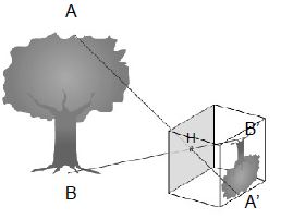
Similarly a ray of light, starting from point B along BH, on passing through pin hole strikes the screen at . Thus, the rays of light starting in between A and B will strike the screen between points and , thereby forming a small diminished image of object AB.
4. Nature of image formed by a Pin Hole Camera:
The image formed by it is real and inverted image. The size of the image depends on the position of the object.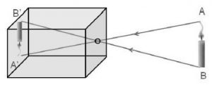
5. Factors affecting the size of the image formed by a Pin Hole Camera:
(a) The size of the image decreases as the object distance increases.
(b) The size of image increases as image distance increases.
6. Magnification of Image: The ratio between the height of the image and height of the object is called magnification. It represents the number of times an image is magnified (or diminished) with respect to size of the object.
Magnification =
7. Advantages of Pin Hole Camera
1. It does not require any lens and hence, the image is completely free from the defects of lenses.
2. It can take very sharp pictures of still objects.
3. It is cheap and easy to construct and operate.
8. Disadvantages of Pin Hole Camera
1. The time of exposure is too large and uncertain. Thus, the final image is either over-exposed or underexposed.
2. It cannot take pictures of the moving objects.
3. It is cumbersome and not easy to operate.
4. If pin hole becomes wider, then the final image is blurred.
5. REFLECTION OF LIGHT
When a beam of light is incident on a surface, a part of it is returned back into the same medium. The part of light which is returned back into the same medium is called the reflected light.
The remaining part of light is absorbed if the surface on which the incident light strikes is opaque or it is partly transmitted and partly absorbed if the surface is transparent.
Reflection: The return of light into the same medium after striking a surface is called reflection.
Reflection of light is the process which enables us to see different objects around us. Luminous bodies are directly seen, but non luminous objects are seen only because they reflect the light incident on them which on entering into our eyes, make them visible.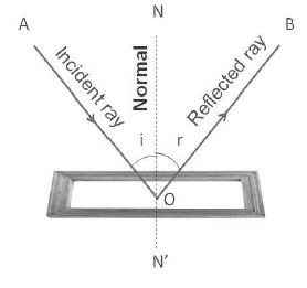
Note: Reflection is possible in case of plane mirror. A plane mirror is a plane glass plate which is silvered at its one surface. The other surface is then reflecting surface of the plane mirror.
Types of Reflections
(a) Regular Reflection
The phenomenon due to which a parallel beam of light travelling through a certain medium, on striking some smooth polished surface, bounces off from it, as parallel beam, in some other direction is called regular reflection.
Regular reflection takes place from the objects like looking glass, still water, oil, highly polished metals, etc.
Regular reflection is useful in the formation of images, e.g., we can see our face in a mirror only on account of regular reflection. However, it causes a very strong glare in our eyes.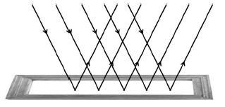
(b) Irregular Reflection or Diffused Reflection:
The phenomenon due to which a parallel beam of light, travelling through some medium, gets reflected in various possible directions, on striking some rough surface is called irregular reflection or diffused reflection.
The reflection which takes places from ground; walls; trees; suspended particles in air; and a variety of other objects, which are not very smooth, is irregular reflection.
Irregular reflection helps in spreading light energy over a vast region and also decreases its intensity. Thus, it helps in the general illumination of places and helps us to see things around us.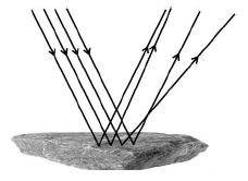
6. GENERAL TERMS TO THE REFLECTION
(a) Mirror: A smooth polished surface from which regular reflection can take place is called mirror. MM| is the mirror as shown in figure.
(b) Incident Ray: A ray of light which travels towards the mirror is called incident ray. AB is an incident ray in the figure.
(c) Point of Incidence: The point on the mirror, where an incident ray strikes is called point of incidence. ‘B’ is the point of incidence in the figure.
(d) Reflected Ray: A ray of light which bounces off the surface of a mirror, is called reflected ray. BC is reflected ray in the figure.
(e) Normal: The perpendicular drawn at the point of incidence, to the surface of mirror is called normal. BN is the normal in the figure.
(f) Angle of Incidence: The angle made by the incident ray with the normal is called angle of incidence. is the angle of incidence in the figure.
(g) Angle of Reflection: The angle made by the reflected ray with the normal is called angle of reflection. is the angle of reflection in the figure.
(h) Glance Angle of Incidence: The angle which the incident ray makes with the mirror is called glance angle of incidence. MBA is the glance angle of incidence in the figure.
(i) Glance Angle of Reflection: The angle which the reflected ray makes with the mirror is called glance angle of reflection. M’BC is the glance angle of reflection in the figure.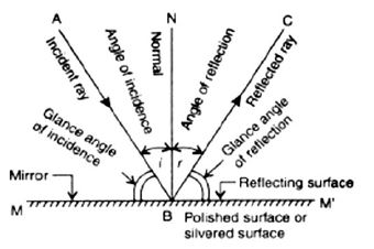
7. LAWS OF REFLECTION
1. The incident ray, the reflected ray and the normal lie in the same plane, at the point of incidence.
2. The angle of incidence is always equal to the angle of reflection.
Formula for the angle of deviation due to Reflection
In the figure angle of incidence = i; Angle of deviation = d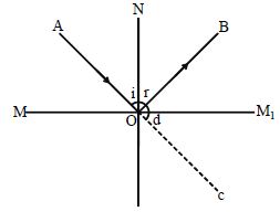
Consider the straight line AOC, i + r +d = 180°
i.e., the sum of angle of incidence, angle of reflection and angle of deviation is 180°.
d = 180 – (i + r) = 180 – (i + i) (i = r)
d = 180 – 2i
Therefore, for an angle of incidence i, the angle of deviation is equal to 180 – 2i =
Note: The deviation produced by n reflections from two plane mirrors inclined at an angle is given by D = n(180 – ) = 360 – 2 , if n = 2 where n is even.
8. IMAGE
When the rays of light, diverging from an object point, after reflection or refraction, either actually meet at some other point, or appear to meet at some other point, then that point is called image of that object.
Types of Images
a) Virtual Image: When the rays of light, diverging from a point, after reflection or refraction, appear to diverge from another point, then the image so formed is called virtual image.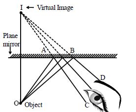
In figure the image ‘I’ of the object ‘O’ is virtual image. The ray of light diverging between OA and OB, after reflection, further diverges along AC and BD respectively.
However, when these diverging rays of light reach the eye, then to the eye they appear to diverge out from point ‘I’. Thus I is virtual image of object ‘O’.
Example: Image of our face in a plane mirror. Virtual images cannot be formed on a screen.
Virtual images are always erect upright. w.r.t object The path of the rays forming a virtual image is shown by dotted lines.
b) Real Image: When the rays of light, diverging from an object point, after reflection or refraction actually converge at some other point then that point is real image of that object.
In figure the ray of light diverging from point A, after reflection from the concave mirror actually converge at the point . Thus, A1 is the real image of the point A.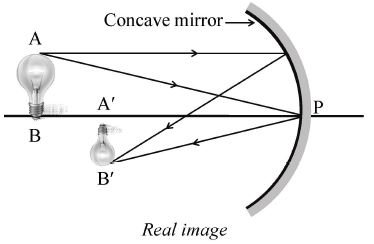
Example: Motion and still pictures projected on the screen in a cinema hall are real images.
Real images are always inverted (upside down) w.r.t object . Real images and the path of the rays which form them are shown by continuous lines.
DISTINCTION BETWEEN REAL IMAGE AND VIRTUAL IMAGE
|
S. No |
Virtual image |
Real image |
|
1
|
The rays of light after reflection or refraction appear to meet at some other point. |
The rays of light after reflection or refraction actually meet at some point. |
|
2. |
It cannot be caught on the screen. |
It can be caught on the screen. |
|
3. |
It is always erect. |
It is always real. |
|
4. |
Image of our face in plane mirror is a virtual image. |
Image formed on a cinema screen is a real image. |
Characteristics of an image formed by a Plane Mirror
1. The image is formed behind the mirror and has the same size as the object
2. The image is inverted laterally.
3. The image is as far behind the mirror as the object is in front of it.
4. The image is virtual. It cannot be received on a screen.
5. The image is erected w.r.t object
9. SHADOWS
We know that light rays travel in straight lines. Thus, if an opaque body is placed in the path of light rays, a dark patch is formed behind the opaque body.
Dark patch formed behind on opaque body, when the opaque body is placed in the path of light is called shadow.
There are two parts for a shadow.
1. Umbra: A region of total darkness, formed behind an opaque body, is called umbra. No rays of light reaches in this region.
2. Penumbra: A region of partial darkness, formed behind an opaque body, is called penumbra. Some rays of light always reach in this region and partially illuminate it.
Conditions for the formation of a Shadow
1. There must be a source of light.
2. There must be an opaque object to obstruct the path of light.
3. There must be a screen to receive the shadow.
Characteristics of a Shadow
When an opaque object is placed between a point light source and a screen, the shadow formed is
1. Uniformly dark
2. Sharp at the edges and
3. Of the same shape as the object.
When an opaque object, larger than the light source, is placed between the light source and the screen, two patches are formed; umbra and penumbra.
Formation of shadow by a Point Source of Light
When an opaque object is placed between a point light source and the screen, the shadow formed is
(i) Uniformly dark
(ii) Sharp at the edges and
(iii) Of the same shape as the object.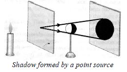
Characteristics of Shadow
(i) Only umbra is formed.
(ii) The size of umbra increases, if the distance of screen from an opaque body increases and vice versa.
(iii) The size of umbra increases, if the distance of the point source of light from an opaque body decreases and vice versa.
Formation of Shadow by Extended Source of Light
An electric bulb or a burning candle, etc., are examples of luminous bodies acting as extended source of light. An extended source is made up of a large number of point sources. There can be the following two situations in case of an extended source of light.
(i) When the extended source of light is smaller in size than the opaque body.
(ii) When the extended source of light is bigger in size than the opaque body.
(a) When extended Source is smaller than Opaque Body:
When an opaque object, larger than the light source, is placed between the light source and the screen (position A), two patches are formed
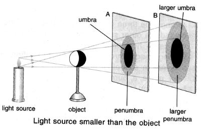
(i) The inner patch is completely dark as it does not get any light. This region is called umbra.
(ii) The outer patch is not completely dark as it receives some light. This lighter patch of shadow is called penumbra.
If the screen is moved away from the object (position B), both the umbra and penumbra increase in size
Characteristics of Shadow
(i) Both umbra and penumbra are formed. However, size of the umbra is very large as compared to penumbra.
(ii) If the screen is moved away from the opaque body, both umbra and penumbra increase and vice versa.
(iii) If the source of light is moved towards opaque body, both umbra and penumbra increase and vice versa.
(b) When extended source is bigger than Opaque Body:
When an opaque object smaller than the light source is placed between the light source and the screen (position A), the umbra and the penumbra are formed.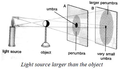
The umbra is very small. If the screen is moved away from the object and from the light source (position B), the size of the umbra becomes smaller and smaller. Beyond a point, the umbra completely vanishes.
Characteristics of Shadow
(i) Both umbra and penumbra are formed. However, size of the umbra is smaller than the penumbra.
(ii) If the source of light is moved towards the opaque body, the penumbra increases, but the umbra decreases.
(iii) If the screen is moved away from the opaque body, the penumbra increases and the umbra decreases, till a stage comes when no umbra is formed.
Note: We cannot see the shadow or a kite of a bird flying high up in the air because the umbra is absent and the penumbra is too large and too faint to be visible.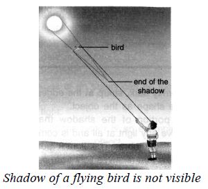
Eclipses
Eclipses are examples of the formation of shadows in the universe. The earth and the moon are opaque, non–luminous bodies and the sun is a luminous body. The earth and the moon cast their shadows leading to the phenomena of eclipses. At times, the sun, the earth and the moon come to lie in a straight line. The object in between casts a shadow and causes an eclipse. There are two kinds of eclipses, the lunar and solar eclipse.
Lunar Eclipse
The lunar eclipse occurs when the sun, earth and moon are in a straight line, with the earth in between the sun and the moon. The shadow of the earth is cast on the moon. If the moon is in the umbra cone of the earth, it will not be visible because the moon is non–luminous and since it does not receive any light from the sun, it does not reflect any light. This is called a total lunar eclipse.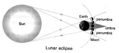
If the moon is slightly out of line, it will not be completely in the umbra cone of the earth. It then receives some light from the sun which it reflects to the earth and makes itself partially visible. This is called a partial lunar eclipse.
A lunar eclipse can occur only on a full moon day.
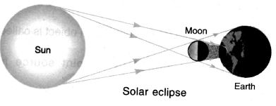
Solar Eclipse
A solar eclipse occurs when the sun, earth and the moon are in a straight line, with the moon between the sun and the earth. The shadow of the moon is cast on the earth. The portion of the earth falling completely in the umbra region has total solar eclipse. The sun appears as a black circular disc with a ring of light. The portion of the earth falling in the penumbra region has partial solar eclipse. A solar eclipse can occur only on a new moon day.