


1. MAGNETIC EFFECT OF CURRENT
Hans Oersted, in 1820, first discovered that when an electric current is passed through a conducting wire, a magnetic field is produced around it. If a compass needle is kept in the vicinity of the current carrying wire, the needle is found to deflect in a definite direction. If the direction of current in the wire is reversed, Then the direction of deflection of the needle is reversed.
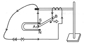
AB is a wire lying in the north-south direction and connected to a battery through a rheostat and a tapping key. A compass needle is kept just below the wire. When the key is open i.e. no current is passed through the wire, the needle shows no deflection and points in the N-S direction (i.e. remains parallel to the wire)as shown in figure(a).
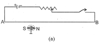
When the key is pressed and current passes in the wire in the direction A to B (i.e. from south to north and the north pole (N) of the needle deflects towards the west as figure (b). Thus a current (or moving charge) produces a magnetic field. When the direction of current in the wire is reversed by reversing the terminals of the batter, the north pole of the needle deflects towards the east as figure(c).
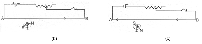
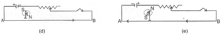
NOTE : If the compass needle is kept just above the wire, the deflection will be as shown in figure (d) and (e) for the direction (e) for the direction of current from A to B and from B to A respectively.
(a) Magnetic Field due to a Straight Current Carrying Wire
When a current is passed through a conducting wire, a magnetic field is produced around it. The direction of magnetic field due to a straight current carrying wire can be mapped by means of a small compass needle or by iron fillings.
Take a sheet of smooth cardboard with a hole at the centre. Place it horizontally and pass a wire vertically through the hole, Sprinkle some iron fillings on the cardboard and pass an electric current through the wire. Gently tap the cardboard. We find that the iron filling arrange themselves in concentric circles around the wire as shown in figure.
If a small compass needle is kept anywhere on the board near the wire, the direction in which the north pole of the needle points gives the direction of the magnetic the magnetic field (i.e., magnetic lines of force) at that point.
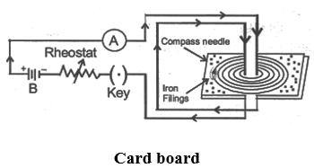
The magnetic lines of force form concentric circles near the wire, with their plane perpendicular to the straight conductor and with their centers lying on its axis. if the direction of current in the wire is reversed, the direction of lines of force is also reversed.
On increasing the strength of current in the wire, the lines of force becomes denser and iron fillings are arranged in circles upto a larger distance from the wire, showing that the magnetic field strength has increased.
(i) Magnitude of magnetic field produced by a straight current-carrying conductor : The magnitude of magnetic field (or strength of magnetic field ) B produced by an infinitely long conductor in vacuum at a distance r from it, it given by :-
B = B = Magnetic field strength = Permeability of vacuum (a constant)
I = Current (flowing in conductor) and
r = Distance from the conductor (where magnetic field is measured).
The unit of magnetic field B is tesla which is denoted by the symbol T (1 tesla is equal to 1 Newton per ampere per meter). Permeability of vacuum is tesla metre per ampere.
(ii) Direction of magnetic field :
The direction of magnetic field (lines of force) produced due to flow of current can be known by the following rules :
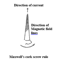
(A) Maxwell’s cork screw rule
Imagine a right handed cork screw lying with its axis coincides with the current carrying wire. It is now rotated such that it advances in the direction of the current, the direction in which the screw rotates gives the direction for the magnetic lines of force.
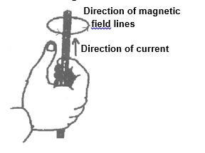
(B) Right hand thumb rule
If we hold the current carrying conductor in the right hand such that the thumb points in the direction of current, the fingers encircle the wire in the direction of magnetic lines of force.
(C) Ampere’s swimming rule
Imagine a man swimming along the wire in the direction of current (such that the current enters at his feet and leaves him at his head) facing towards a magnetic needle kept underneath the wire, then the magnetic field produced in such that the north pole of the needle will be deflected towards his left hand. 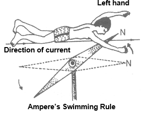
(b) Magnetic Field due to Circular Coil Carrying Current
A piece of wire bent in the form of a ring (or coil) is passed through a horizontal cardboard C at two points P and Q at the opposite ends of a diameter of the ring and then some iron fillings are scattered on the cardboard. The ends of the coil are connected to a battery through a rheostat and a key.
When a strong electric current is passed through the coil by closing the key and the cardboard is gently tapped we find that the iron filing arrange themselves in a definite pattern representing the magnetic lines of force due to the current carrying coil.
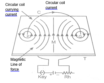
Direction of magnetic field is found by applying the right hand thumb rule to each section of the coil and we find that the concentric lines of force pass through the coil in the same direction. Further more that :
(i) The magnetic lines of force are nearly circular near the wire.
(ii) Within the space enclosed by the wire, the lines of force are in the same direction.
(iii) Near the center of the coil, the lines of force are nearly parallel and the magnetic field may be assume to be practically uniform for a small space around the centre.
(iv) At the centre, the lines of force are along its axis and at right angle to the plane of the coil.
(v) The magnetic field strength is increased if the number of turns in the coil is increased or the strength of current in the coil is increased.
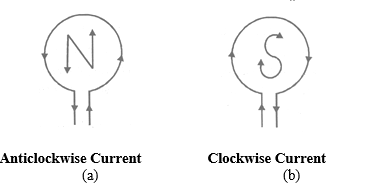
Since the magnetic lines of force through the coil point in the same direction, hence one face of the coil acts as a large area of north polarity because it is sending out magnetic lines of force and the other face acts as a large area of south polarity as magnetic lines of force are entering it. thus, the coil has a magnetic field similar to a magnetised iron disc of same radius as that of the coil.
The polarity of the faces of the coil depends on the direction of current and is determined by the clock rule. Looking at the face of the coil, if the current around the face is in an anticlockwise direction, the face has north polarity, while if the current at that face is in the clockwise direction, the face has south polarity. This can e tested by using a compass needle.
The magnitude of magnetic field B produced by a current-carrying circular wire at its centre is :
(i) directly proportional to the current I passing through the circular wire and
(ii) inversely proportional to the radius r of the circular wire.
i.e. B I and B
Magnetic field, B =
Formula which we have given above is applicable when there is only one turn of a circular wire. If we have circular coil having N turns of wire, then the magnetic field will become N times. Thus, the magnetic field at the centre of a circular coil of N turns having radius r and carrying current I is given by
Magnetic field produced by a circular coil carrying current is directly proportional to both, number of turn (N) and current (I), but inversely proportional to its radius (r). Thus, the strength of magnetic field produced by a current carrying circular coil can be increased by (i) increasing the number of turns of wire in the coil, (ii) increasing the current following through the coil and (iii) decreasing the radius of the coil.
(c) Magnetic Field due to a Solenoid Carrying Current
If a conducting wire is wounded in the form of a cylindrical coil whose diameter is less in comparison to the length, then this coil is called a solenoid (it looks like a helical spring).
The magnetic field lines in a solenoid, through which current is passed, are as shown in figure.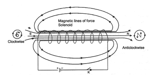
The magnetic field, thus produced, is very much similar to that of a bar magnet and one end of the coil acts like a magnetic north pole while the other acts like a south pole.
The lines of force inside the solenoid are nearly straight and parallel to the axis of the solenoid.
A strong magnetic field can be obtained by increasing the current strength.
The magnetic field is increased if the number of turns in the solenoid of given length is increased.
The magnetic field is also increased if soft iron core is kept along the axis of the solenoid.
Thus a current carrying solenoid behaves like a bar magnet with fixed polarities at its ends. 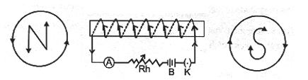
The strength of magnetic field produced by a current carrying solenoid depends upon :
(i) The number of turns in the solenoid : Larger the number of turns in the solenoid, greater will be the magnetic field produced.
(ii) The strength of current in the solenoid : Larger the current passed through solenoid, stronger will be the magnetic field produced.
(iii) The nature of “core material” used in making solenoid : The use of soft iron rod as core in a solenoid produced the strongest magnet.
Magnetic field inside the solenoid is :
B = n I [Here in is number of turns per unit length]
At the ends of the solenoid the magnetic field :
2. PERMANENT AND TEMPORARY MAGNETS
The degree to which magnetism is retained by a given piece of iron depends entirely upon its constitution. Steel retains the largest amount while soft iron retains the least. Therefore pieces of steel are employed to prepare permanent magnets, whereas soft iron is used for preparing temporary magnets, i.e., magnets that retain their magnetism only as long as the current flows in the magnetising coil. They lose their magnetism as soon as the current is switched off. Such magnets are known as electromagnets.
(a) Electromagnet
An electric current can be used for making temporary magnets known as electromagnets. As electromagnet works on the magnetic effect of current. When current is passed through a long coil called solenoid, a magnetic field is produced. It has been found that if a soft iron rod called core, is placed inside a solenoid then the strength of magnetic field becomes very large because the iron core gets magnetised by induction. This combination of a solenoid and a soft iron core is called an electromagnet.
Electromagnets can be made in different shapes and sizes depending on the purpose for which they are to be used.
Factors affecting the strength of an electromagnet are :
(i) The number of turns in the coil: If we increase the number of turns in the coil, the strength of electromagnet increases.
(ii) The current flowing in the coil : If the current in the coil is increased, the strength of electromagnet increases.
(iii) The length of air between its poles : if we reduce the length of air gap between the poles of an electromagnet, then its strength increases.
For example, the air gap between the poles of straight bar type electromagnet is quite large, so a bar type electromagnet is not very strong. One the motherland the air gap between the poles of a U-shaped electromagnet is small, so it is a very strong electromagnet.
Electromagnets are used in electric bells, telegraphs, telephones and several other instruments. Since the magnetisation depends on the current flowing through the coil, it is possible to obtain very powerful electromagnets by increasing the current.
Soft iron can be easily magnetised every by a weak magnetic field, whereas steel can be magnetised only by strong magnetic field.
Less energy is required for magnetising soft iron. Soft iron loses its magnetism immediately, whereas steel retains it magnetism.
(b) Difference between a Bar Magnet (or Permanent Magnet) and an Electromagnet
|
S.No. |
Bar magnet (or permanent magnet) |
Electromagnet |
|
(1) |
The bar magnet is a permanent magnet.
|
An electromagnet is a temporary magnet. Its magnetism is only for the duration for which current passes through it, so the magnetism of an electromagnet can be switched on or switched off as desired. |
|
(2) |
A permanent magnet produces a comparatively weak force of attraction. |
An electromagnet can produce very strong magnetic force.
|
|
(3) |
The strength of a permanent magnet cannot be changed. |
The strength of an electromagnet can be changed by changing the number of turns in its coil or by changing the current passing through it. |
|
(4) |
The (north-south) polarity of permanent of manget is fixes and cannot be changed. |
The polatiry of an electromagnet can be changed by changing the direction of current in its coil. |
Permanent magnets are usually made of alloys such as carbon-steel, chromium-steel, cobalt-steel, tungsten-steel, nipermag and alonico. Nipermag is an alloy of iron, nickel, aluminum and titanium whereas ALNICO is an alloy of aluminum, nickel and cobalt. Permanent magnets of these alloyws are much more stronger than those made of ordinary steel, such strong permanent magnets are used in microphones, loudspeakers, electric clocks, ammeters, voltmeters, speedometers and many other devices.
(c) Methods of Demagnetising a Permanent Magnet
(i) Magnet can be demagnetised by :
(A) Self – demagnetisation, if the magnet is strode without using magnetic keepers.
(B) Dropping it from a height or by rough handling.
(C) Heating or hammering the magnet.
(ii) Magnet can be demagnetised by placing it within a solenoid and passing high frequency AC through it.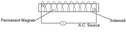
3. USED OF MAGNETISM IN MEDICINE
An electric current always produces a magnetic field. Even weak ion currents that travel along the nerve cells in our body produce magnetic fields.
When we touch something, our nerves carry an electric impulse to the muscles we need to use. The impulse produces a temporary magnetic field. These field are very weak and are one billionth of the earth’s magnetic field. Heart and brain are the two main organs in the human body where the magnetic field produced is significant. The magnetic field inside the body forms the base of obtaining the images of different body parts. This is done by using a technique called Magnetic Resonance Imaging (MRI). Analysis of these images helps in medical diagnosis. Magnetism has thus, got important uses in medicine.
4. MAGINETIC FORCE
(a) Force on a Current-Carrying Conductor in a Magnetic Field
Immediately after Oersted’s discovery of electric currents producing magnetic fields and exerting forces on magnets, Ampere suggested that magnet must also exert equal and opposite force on a current-carrying conductor. When a current carrying conductor is kept in a magnetic field (not parallel to it), a force acts on it. This force is created due to the interaction of magnetic field of the current in the conductor and the external magnetic field on the conductor. As a result of this superposition, the resultant magnetic field on one side of conductor is weaker than on the other side. hence the conductor experience a resultant force in one direction.
Take a small aluminum rod AB. Suspend it horizontally by means of two connecting wires from a stand. Now, place a strong horseshoe magnet in such a way that the rod is between the two poles with the field directed upwards. If a current is now passed in the road from B to A, we will observe that the rod gets displaced. This displacement is caused by the force acting on the current-carrying rod. The magnet exerts a force on the rod directed towards the right, with the result the rod will get deflected to the right. If we reverse the current or interchange the poles of the magnet, the deflection of the rod will reverse, indicating thereby that the direction of the force acting on it gets reversed. This shows that there is a relationship among the directions of the current, the field and the motion of the conductor.
(b) Direction of Force on Current Carrying Conductor
The direction of force obtained by the Fleming’s left hand rule.
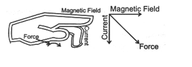
Fleming left hand rule :
Stretch the forefinger, middle finger and the thumb of you lef hand mutually perpendicular to each other as shown in figure. It the forefinger indicates the direction of the magnetic field and the middle finger indicates the direction of current, then the thumb will indicated the direction of motion (i.e., force) on the conductor.
(c) Magnitude of Force
Experimentally it is found that the magnitude of the force acting on a current carrying conductor kept in a magnetic field in direction perpendicular to it, depends on the following factors :
(i) The force F is directly proportional to the current flowing in the conductor, i.e. F I.
(ii) The force F is directly proportional to the intensity of magnetic field, i.e. F B.
(iii) The force F is directly proportional to the length of the conductor (inside the magnetic field), i.e. F ∝ Combining these we get, F ∝ I B Or F = K I B
Where K is constant whose value depends on the choice of units. In S.I. units K = 1 and the unit of magnetic field is tesla (T). 1 tesla is equal to 1 Newton ampere-1 metre-1 or 1 Weber metre-2.
Force is directly proportional to sin where is the angle between current and the direction of magnetic field. i.e. F ∝ sin
Combining all we have F = BI sin or
Special cases :
(i) When or ,
Force on a current – carrying conductor placed parallel or ant parallel to field is zero.
(ii) If , sin 900 = 1, F = BI is the maximum force. Force experienced by the conductor is maximum when placed perpendicular to magnetic field.
(iii) I of B = 0, F = 0 i.e. the coil placed in field free area doesn’t experience any force.
A moving charge in a magnetic field (direction of motion not parallel to the field direction) experiences a force called Lorentz force. Since current is due to flow of charge, therefore a conductor carrying current will experience a force.
The force acting on a current – carrying conductor placed in a magnetic field is :
F = BI
Now, if a charge Q flows in time t then the current I=. So, writing in place of I in the above equation,
we get :
Suppose the particle carrying the charge Q travels a length in time t. Then the velocity v of the charged particle will be equal to . Writing v in place of in the above equation, we get :
Force on moving charge, F = B × q × v
Where B = Magnitude of magnetic field, Q = Charge on the moving particle and v = Velocity of the charged
particle (in metre per second). In vector notation
5. ELECTROMAGNETIC INDUCTION
When an electric current is passed through a conductor, a magnetic field is produced around the conductor. Faraday thought that as a magnetic field is produced by electric current, it should be possible to produce an electric current by the magnetic field. According to him, whenever there is a change in the magnetic lines of force associated with a conductor, an electromotive force (e.m.f.) is set up at the ends of the conductor which lasts as long as the change is taking place. This phenomenon is called electromagnetic induction.
(a) Faraday’s Experiments
Wind an insulated copper wire on a wooden cylinder so as to form a solenoid coil. Connect the two ends of the coil to the centre of galvanometer. A magnet is placed along the axis of the coil.
(i) When the magnet is stationary, there is no deflection in the galvanometer. The pointer reads zero as shown in figure (A).
(ii) When the north pole of the magnet is brought near the coil, the current flows in the coil in direction shown in the figure (B) and the galvanometer shows the deflection towards the right.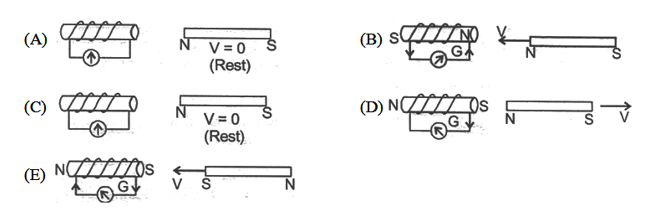
(iii) If we stop the motion of the magnet, the pointer of the galvanometer comes to the zero position as shown in figure (C). Thus the current in the coil flows so long as the magnet is moving. If the magnet is taken away from the coil, the current again flows in the coil but in the direction opposite to that shown in figure (D) and therefore the pointer of the galvanometer deflects towards the left side.
(iv) If south pole of the magnet is brought towards the coil, the current in the coil flow in the direction opposite to that shown in figure (E) and so the pointer of the galvanometer deflects towards the left.
(v) Similar deflection is observed in the galvanometer if the magnet is kept stationary and the coil is moved.
From this experiment Faraday concluded that :
(i) The galvanometer shows a deflection (i.e. current flow in the coil) only when there is relative motion between the coil and the magnet.
(ii) The direction of deflection is reversed if the direction of motion is reversed.
(iii) The value of the current in the coil (i.e. deflection of the pointer) is increased by :
(A) The rapid motion of the magnet or the coil.
(B) the use of a strong magnet.
(C) increasing the area and number of turns in the coil.
When the magnet and coil are relatively at rest, the total number of magnetic lines of force due to the magnet passing through the coil (i.e. the magnetic flux linked with the coil) remains constant, therefore no e.m.f. is induced in the coil and the galvanometer shows no deflection.
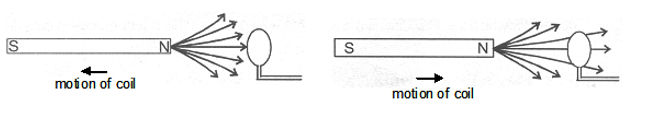
When there is relative motion between the coil and magnet, the magnetic flux linked with coil changes. If the coil is moved towards the magnet, the magnetic flux through the coil increases as shown in fig. Due to change in magnetic flux linked with the coil, an e.m.f. is induced in the coil. This e.m.f. causes a current to flow if the circuit of the coil is closed.
(b) Faraday’s Laws of Electromagnetic Induction
Faraday formulated the following two laws of electromagnetic induction :
(i) Whenever there is a change in magnetic flux linked with a conductor, an em.f. is induced. The induced e.m.f. lasts so long as there is a change in magnetic flux cut by the conductor.
(ii) The magnitude of the e.m.f. induced is directly proportional to the rate of change of magnetic flux cut by the conductor. If the rate of change of magnetic flux remains uniform, a steady e.m.f. is induced. If the circuit of conductor is closed, a current flows in the conductor due to the e.m.f. induced across its ends.
(c) Direction of Induced e.m.f.
The direction of induced e.m.f. (and hence the direction of induced current) can be obtained by any of the following rules :
(i) Fleming’s right hand rule
(ii) Lenz’s law
(i) Fleming’s right hand rule :
Stretch the thumb, middle finger and the forefinger of your right hand mutually perpendicular to each other as shown in figure. If the forefinger indicated the direction of the magnetic field and the thumb indicated the direction of motion of the conductor, the middle finger will indicate the direction of induced current.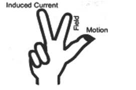
(ii) Lenz’s law : This law gives us the direction of current induced in a circuit.
According to Lenz’s law, the induced current will appear in such a direction that it opposes the change (in magnetic flux) responsible for its production.
The law refers to induced currents, which means that it applies only to closed circuits. If the circuit is open we would find the direction of induced e.m.f.
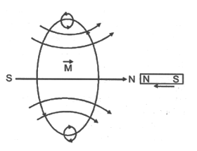
For example, in figure, when the magnet is moved towards the loop, a current is induced in the loop. The induced current produces its own magnetic field with magnetic dipole moment oriented so as to oppose the motion of the magnet. Thus the induced current must be anticlockwise as shown in figure below.
6. GENERATOR
This is a divide which convert mechanical energy into electrical energy using the principle of electromagnetic induction. It is of two types :
AC Generator or Dynamo
When a coil (conductor) is rotated in a magnetic field, the magnetic flux linked with it changes and therefore an alternating e.m.f. is induced in the coil.
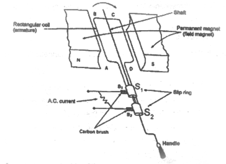
Construction : The main parts of dynamo are :-
(i) Field magnet : It is a strong horse shoe permanent magnet. An electromagnet run by a DC source can also be used for high power generators.
(ii) Armature: It is a soft iron core on which a coil ABCD having a large number of turns of insulated copper wire is wound. This armature (or coil) is rotated rapidly in the magnetic field between the poles of the magnet.
(iii) Slip rings : The ends of the armature (or the coil) are connected to two coaxial metallic slip rings which rotate along with the coil.
(iv) Brushes : Two brushes and made of carbon, press against the slip rings and respectively. The external circuit (i.e. load) is connected between the other ends of brushed. The brushed and do not rotate along with the coil.
Working of an AC generator
Suppose that the generator coil ABCD is initially in the horizontal position. Again suppose that the coil ABCD is being rotated in the anticlockwise direction between the poles N and S of a horse-shoe type magnet.
(i) As the coil rotates in the anticlockwise direction, the side AB of the coil moves down cutting the magnetic lines of force near the N- pole of the magnet and side CD moves up, cutting the lines of force near the S-pole of the magnet. Due to this induced current is produced in the side AB and DC of the coil. On applying Fleming’s right-hand rule to the sides AB and DC of the coil, we find that the currents are in the directions B to A and D to C. Thus, the induced currents in the two sides of the coil are in the same direction and we get an effective induced current in the direction BADC.
(ii) After half revolution, the sides AB and DC of the coil will interchange their positions. The side AB will come on the right hand side and side DC will come on the left hand side. So, after half a revolution, side AB starts moving up and side DC starts moving down. As a result of this, the direction of induced current in each side of the coil is reversed after half revolution. Since the direction of induced current in the coil is reversed after half revolution so that polarity (positive and negative) of the two ends of the coil also changes after half revolution. The end of coil which was positive in the first half of rotation becomes negative in the second half. And the end which was negative in the first-half revolution becomes positive in the second half of revolution. Thus, in 1 revolution of the coil, the current changes its direction 2 times.
The alternating current (AC) produced in India has a frequency of 50 Hz. That is, the coil is rotated at the rate of 50 revolutions per second. Since in 1 revolution of coil, the current changes its direction 2 times, so in 50 revolutions of coil, the current changes its direction 2 × 50 = 100 times. Thus, the AC supply in India changes its direction 100 times in 1 second. Another way of saying this is the alternating current produced in India changes its direction every 1/100 second. That is, each terminal of the coil is positive (+) for 1/100 of a second and negative (-) for the next 1/100 of a second.
After every half revolution, each side of the generator coil starts moving in the opposite direction in the magnetic field. The side of the coil which was initially moving upwards, after half revolution, it starts moving downwards. Due to the change in the direction of motion of the two sided of the coil in the magnetic field every half revolution, the direction of current produced in them also changes after every half revolution.
(b) DC Generator (or DC Dynamo)
“DC generator” means “Direction Current generator”. That is, a DC generator produces direct current
Construction of a DC Generator :
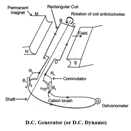
A simple DC generator consists of a rectangular coil ABCD which can be rotated rapidly between the poles north and south of a strong horse-shoe type magnet M.
The generator coil is made of a large number of turns of insulated copper wire. The two ends of the coil are connected to the two copper half rings (or split rings) and commutator. There are two carbon brushes and which press lightly against the two half rings. When the coil is rotated, the two half rings and touch the two carbon brushes and one by one. So, the current produced in the rotating coil can be tapped out through the commulator half rings into the carbon brushes. From the carbon brusher and . we can take the current into the various electrical appliances like radio, T.V., electric iron, bulbs, etc.
 Working of a DC generator
Suppose that the generator coil ABCD is initial in the horizontal position. Again suppose that the coil ABCD is being rotated in the anticlockwise in the anticlockwise direction between the poles N and S of a horse-shoe type magnet.
(i) As the coil rotates in the anticlockwise direction, the side AB of the coil move down cutting the magnetic lines of force near the N-pole of the magnet and side DC moves up, cutting the lines of force near the S-pole of the magnet in figure. Due to this, induced current is produces in the sides AB and DC of the coil. On applying Fleming’s right-hand rule to the sides AB and DC of the coil we find that the currents in them are in the directions B to A and to C respectively. Thus, we get an effective induced current in the direction BADC. Due to this the brush B1 becomes a positive (+) pole and brush B2 becomes negative (-) pole of the generator.
(ii) After half revolution the sides AB and DC of the coil will interchange their positions. The side AB will come on the right hand side and start moving up whereas side DC will come on the left-hand side and start moving down. But when sides of the coil interchange their position, then the two commutator half rings and automatically change their contacts from one carbon brush to the other. Due to this change, the current keeps flowing in the same direction in the circuit. Te brush will always remain positive terminal and brush will always remain negative terminal of the generator. Thus, a DC generator supplies a current in one direction by the use of a commutator consisting of two half-rings of copper.
Difference between a DC generator an AC generator
In a DC generator we connect the two ends of the coil to a commutator consisting of two, half rings of copper. On the other hand, in an AC generator, we connect the two ends of the coil to two full rings of copper called slip rings.
7. ELECTRIC MOTOR
A motor is a device which converts electrical energy into mechanical energy. Every motor has a shaft or spindle which rotates continuously when current in passed into it. The rotation of its shafts is used to drive the various types of machines in homes and industry. Electric motor is used in electric fans, washing machines, refrigerators, mixer and grinder and many other appliances. A common electric motor works on direct current. So, it is also called DC motor, which means a “Direct Current motor”/ The electric motor which we are going to discuss now is actually a DC motor.
(a) Principle of a Motor
An electric motor utilizes the magnetic effect of current. A motor works on the principle that when a rectangular coil is placed in a magnetic field and current is passed through it, a torque acts on the coil which rotates is continuously. When the coil rotates, the shaft attached to it also rotates. In this way the electrical energy supplied to the motor is converted into the mechanical energy of rotation.
(b) Construction of a Motor
An electric motor consists of a rectangular coil ABCD of insulated copper wire, wound on a soft iron core called armature. The soft iron core has not been shown in figure to make things simple. The coil is mounted between the curved poles of a U-shaped permanent magnet is such a way that it can rotate between the poles N and S. The two ends of the coil are soldered (or welded) permanently to the two half rings X and Y of a commutator.
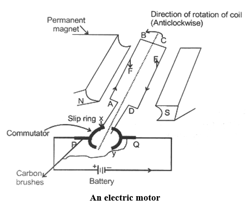
A commutator is a copper ring split into two parts X and Y, these two parts are insulated from one another and mounted on the shaft of the motor.
End A of the coil is welded to part X of the commutator and end D of the coil is welded to part Y of the commutator. The commutator rings are mounted on the shaft of the coil and they also rotate when the coil rotates.
The function of commutator rings is to reverse the direction of current following through the coil every time the coil just passes the vertical position during a revolution.
We cannot join the battery wire directly to the two commutator’s half rings to pass current into the coil because if we do so, then the connecting wires will get twisted when the coil rotates. So, to pass the electric current to the coil, we use two carbon strips P and Q known as brushes. The carbon brushes P and Q are fixed to the base of the motor and they press lightly against the two half rings of the commutator. The function of carbon brushes is to make contact with the rotating rings of the commutator and through them to supply current to the coil. It should be noted that any one brush touches only one ring at a time, so that when the coil rotates, the two brushes will touch both the rings one by one.
(c) Working of a Motor
Suppose that initially the coil ABCD is in the horizontal position as shown in figure. On pressing the switch, the current enters the coil through carbon brush P and commutator half ring X. The current flows in the direction ABCD and leaves via ring Y and brush Q.
(i) In side AB of the coil, the direction of current is from A to B and the direction of magnetic field is from N to S pole. So, by applying Fleming’s left hand rule to the side AB of the coil we find that it will experience a force in the upward direction.
(ii) In side DC of the coil, the direction of current is from C to D towards but the direction of magnetic field remains the same from N to S pole as shown in figure. So, by applying Fleming’s lef hand rule to the side DC of the coil, we find that. It will experience a force in the downward direction.
(iii) We find that the force acting on the side AB of the coil is in the upward direction whereas the force acting on the side DC of the coil is in the downward direction. These two equal, opposite and parallel forces acting on the two sided to the coil form a couple (torque) and rotate the coil in the anticlockwise direction.
(iv) While rotating, when the coil reaches the vertical position, then the brushes P and Q will touch the gap between the two commutator rings and current to the coil is cut off. Though the current to the coil is cut off when it is in the exact vertical position, the coil doesn’t stop rotating because it has already gained momentum due to which it goes beyond the vertical position.
(v) When the coil goes beyond the vertical position, the two commutator’s half rings automatically change contact from one brush to the other. This reverses the direction of current through the coil which, in turn, reverses the direction of forces acting on the two sides of the coil. The side AB of the coil now be one the left hand side with a downward force on it, whereas side DC of the coil will come on the right hand side with an upward force on it. In this position also a couple acts on the coil which rotates it in the same direction (anticlockwise direction). This process is repeated again and again and the coil continues to rotate as long as the current is passing. This is how an electric motors works.