1. INTRODUCTION
In electrostatics, our discussion of electric phenomena has been focused on charges at rest. In the previous chapter, we treated the concept of electric potential, which is measured in volt. Now we will see that this voltage acts like an “electrical pressure” that can produce a flow of charge or current, which is measured in ampere (or simply, amp and abbreviated as A) and that the resistance that restrains this flow is measured in ohm ().
The net flow charge in a direction through a metallic wire constitutes an electric current. The branch of physics which deals with the study of charges in motion is called current electricity.
The electric currents occur naturally many situations. For example, in case of lightning, charges flow from the clouds to the earth through the atmosphere, which sometimes produces disastrous results. The flow of charges in lightning is of short duration, resulting in a current flow called transient current. The transient current ceases when the flow of charges stops. There are many devices, which we use in our daily life, where the charges flow in a steady manner. For example, a cell driven clock, a torch etc.
2. ELECTRIC CHARGE
The distribution of charge in a body is measured in coulombs. The quantization of charge requires that a charge on a body always remain the integral multiple of charges in an electron.
Therefore, we have the relation
Q = ne
Where, Q is the charge on the body
n is the number of electrons
e is the charge on electrons (1.6 ×)
The SI unit of electric charge is coulomb, denoted by the letter ‘C’.
Number of electrons in 1 C charge
Total charge possessed by one electron = 1.6 × C
i.e., 1 electron = 1.6 × C
⇒ electrons
or, 1 C = 6.25 × electrons
Hence, we can say that one coulomb of electric charge contains 6.25 × electrons.
3. ELECTRIC CURRENT
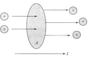
An isolated metallic conductor, say a wire, contains a few electrons which are moving at random with high speeds. These are called conduction electrons. The rate at which these electrons pass from left to right through an area in a wire is the same as the rate at which they pass from right to left through the same area, i.e., net rate is zero. Charges in motion through an area A.
The time rate at which charge flows through the area is defined as the current I. The direction of the current is the direction in which positive charges flow when free to do so.
Electric current=
Consider, both the positive and negative charges be flowing forward and backward normally across a small area. In a time interval t, let q+ be the net amount (i.e., forward minus backward) of positive charge that flows in the forward direction across the given area and let be the net amount of negative charge that flows in the forward direction across the area. The net amount of charge flowing across the given area in time t in the forward direction is q = q+
Electric current, I= __________ (1)
If in a solid conductor n number of free electrons each of charge e move towards the positive end of conductor in time t, then net charge flown ; q = ne.
Electric current, I=
If the value of q is positive, then the direction of current is forward. In equation (1), if the value of q comes out to be ve, then the direction of current is backward.
Current Through A Wire
When a wire is connected to a battery, an electric field is set up at every point within the wire. This field exerts a force on each conduction electron. Although the electrons are continuously accelerated by the field, due to their frequent collisions with the atoms of the wire, they on an average simply drift at a small constant speed in the direction opposite to the field.
Thus, there is a net flow of charge in the wire at a small rate. The total charge passing through any cross section per second is the electric current in the wire.
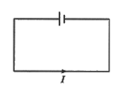
In the steady state, current through each section of the conducting loop would be same—no matter what is the location or orientation of area of that section see Figure. This is because of the fact that charge is conserved.
Unit of Electric Current
In SI system, it is ampere (A).
“The current is said to be one ampere when one coulomb of charge flows past any cross section of a conductor every second.”
4. CONDUCTORS AND INSULATORS
In some substances, the electric charges can flow easily while in other they cannot. S, all the substances can be divided mainly into two electrical categories: Conductors and insulators.
(i) Conductors : Those substances through which electric charges can flow, are called conductors. But the flow of electric charges is called electricity. All the metals like silver copper and aluminum etc., are conductors. Carbon, in the form of graphite, is a conductors and the aqueous solution (water solution) of salts are also conductors. The human body is a fairly good conductor. All the conductors (like metals) have some electrons which are loosely held by the nucleus of their atoms. These electrons are called “free electrons” and can move from one atom to another atom throughout the conductor. The presence of “free electrons” in a substance makes it a conductor of electricity.
(ii) Insulators : Those substances through which electric charges cannot flow, are called insulators. In other words, those substances through which electricity cannot flow are called insulators. Glass, ebonite, rubber, most of the plastics, paper, dry wood, cotton, mica, bakelite, and dry air, are all insulators because they do not allow electric charges (or electricity) to flow through them. In the case of charged insulators like glass, ebonite etc., the electric charges remain bound to them and do not move away.
The electrons present in insulators are strongly held by the nuclei of their atoms. Since there are “no free electron” in an insulator which can move from one atom to another, so insulator does not allow electric charges (or electricity) to flow through it.
NOTE : Those substance whose conductivity lies in between the conductors and insulators are called semi-conductors.
For e.g. : Silicon, germanium are semi – conductors.
5. ELECTRIC CURRENT IN CONDUCTORS
We know that atoms and molecules are made of negatively charged electrons and positively charged nuclei, which are bound to each other and are thus not free to move. A material (i.e., a bulk matter) is composed of many atoms/molecules. In a material, the molecules are so closely packed that some of the electrons in it are no longer attached to individual nuclei, but free to move inside the matter like molecules in a gas. Such electrons are called free electrons. These free electrons move under the effect of electric field, in a definite direction, resulting in a current in the material. Those materials which have large number of free electrons and develop strong electric currents in them, when an electric field is applied are generally called conductors.
There are some other materials in which the electrons will be bound and they will not be accelerated, even if the electric field is applied, i.e., no current on applying electric field. Such materials are called insulators. For example, wood, plastic, rubber etc.
In case of a solid conductor (i.e., Cu, Fe, Ag etc.) atoms are tightly bound to each other. There are large number of free electrons in them, which will be responsible for the strong current in them when electric field is applied on them.
In case of a liquid conductor like electrolytic solution, there are positive and negative charged ions which can move on applying electric field, causing the electric current.
Here, we will discuss only about solid conductors in which the positive ions are at fixed positions and the current is carried by the negatively charged electrons.
When no electric field is applied on a solid conductor, the free electrons move like molecules in a gas due to their thermal velocities. There is no preferential direction for the velocities of the electrons. The average thermal random velocity is zero. Due to it, there is no net flow of electric charge in a direction inside the conductor and hence no current in it.
When an electric field is applied on a solid conductor in the shape of a cylinder of circular cross-section by attaching positively and negatively charged circular discs of a dielectric of the same radius as that of the solid conductor, at the two ends as shown in Figure. An electric field is set up in the conductor from positive charged disc towards negative charged disc.
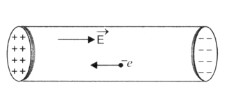
Due to this electric field, the free electrons in the conductor will be accelerated towards the positive disc side, in order to neutralise the charges of discs. The motion of the electrons will be there till the electric field inside the conductor exists. In this situation, there will be a current for a very short time called transient current in the conductor.
If we apply a steady electric field in the body of conductor by connecting a cell or battery across the two ends of a conductor, then there will be a steady current in the conductor rather than a transient current.
6. ELECTRIC POTENTIAL AND POTENTIAL DIFFERENCE
The flow of electricity in a circuit can be regarded very mush similar to the flow of water in a pipe. The water pipe is analogous to the electric conductor, while the amount of water flowing through a given point per second corresponds to electric current. Figure below show how the pump (P) builds up and maintains pressure by lifting water from a tank (B) to the reservoir (A) through the pipe (R).Note that along the pipe, different points are at different pressure. Water in the pipe flow from say, a point C to D only when the pressure at C is greater than that at D. Thus, when the value (V) is open, water start flowing into the reservoir.
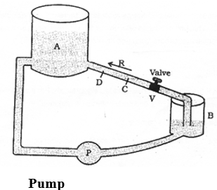
In the same manner electrons will move along a wire only if there is a difference of electric pressure called potential difference along the conductor. This difference of potential produced by the cell or a battery, which acts like a water pump in the circuit.
The chemical action within the cell generates the difference in potential between the electrodes, which sets the electrons in motion and produces the current We define the electric potential difference between the two points, A and B, on a conductors carrying current, as the work done to move a unit charge from A to B. Potential difference (V) between the points A and B = work done (W)/charge (Q). The unit of potential is volt, named after a scientist Alessandra (1745 – 1827).
One volt is the potential difference when 1 joule of work is done to move a charge of 1C.
Electric Potential
The electric potential at a point in an electric field is defined as the amount of work done in moving a unit +ve charge from infinity to that point, without acceleration or without a change in K.E., against the electric force due to the electric field.
V=
Since work is measured in joule and charge in coulomb, therefore electric potential is measured in joule per coulomb (J/C). This unit occurs so often in our study of electricity, so it has been named as volt, in honour of the scientist Alessandra Volta (the inventor of the voltaic cell).
1 Volt =
Potential is a scalar quantity, therefore it is added algebraically. For a positively charged body potential is positive and for a negatively charged body potential is negative.
Electric Potential Difference
Consider a charge Q placed at a point P. Let A and B be two other point (B being closer to A) as shown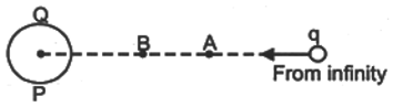
If a charge q is brought from infinity to A, a work WA will be done.
The potential at A will then be,
If charge q is brought from infinity to B, the work done will be WB.
The potential at B will be,
The quantity VB – VA is called the potential difference between points A and B in the electric field of charge Q.
Mathematically we have, VB – VA =
Electric potential difference is also measured in volt.
7. ELECTRICAL CIRCUITS
Electrical Symbols
The various electrical symbols used in electric circuits are given below :
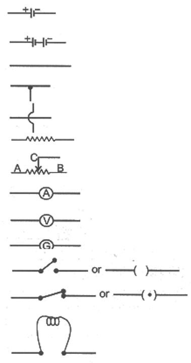
(i) Cell
(ii) Battery
(iii) Connecting wire
(vi) A wire joint
(v) Wire crossing without contact
(vi) Fixed resistance (or Resistor)
(vii) Variable resistance (or Rheostat)
(viii) Ammeter
(ix) Voltmeter
(x) Galvanometer
(xi) An open switch (An open plug key)
(xii) A closed switch ( A closed plug key)
(xiii) Electric bulb
Electrical circuits
A continuous path consisting of conducting wires and other resistances (like lamps, bulbs etc.) between the terminal of a battery, along which an electric current flows, is called a circuit.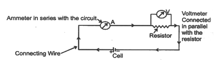
(a) Open Electric Circuit
An electric circuit through which no electric current flows is known as open electric circuit. The electric circuit will be open circuit if the plug of the key is taken out or if the connecting wire break from any point.
(b) Closed Circuit
An electric circuit through which electric current flows continuously is known as closed circuit.
8. ELECTRICAL RESISTANCE
(a) Ohm’s Law
It states that the current passing through a conductor is directly proportional to the potential difference across its ends, provided the temperature and other physical conditions (mechanical stain etc.), remain unchanged i.e.,
Where R is a content called resistance of the conductor.
The relation R = V/I is referred to an Ohm’s law, after the German physicist George Simon Ohm (1789 -1854), who discovered it.
It is quite clear from the above equation that
(i) The current I is proportional to the potential difference V between the ends of the resistor.
(ii) Current I is inversely proportional to the resistance.
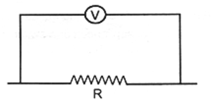
Experimental verification of ohm’s law
Set up a circuit as shown in the figure below consisting of a wire AB, a current measuring instrument called ammeter, an instrument measuring the potential difference called voltmeter and a number of cells, each of which provided some constant potential difference across the two point of a conductor. First, use one cell and note the current in the circuit and the potential difference across the wire AB. Suppose potential difference due to the cell produces a current I in the circuit and a potential difference (V) across the wire AB. Repeat this experiment with two cells, three cells and four cells.
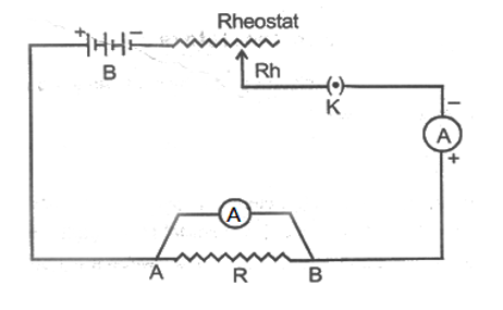
Note the successive readings in the ammeter and the voltmeter. WE will find that with two cells in the circuit, the current would be 2I and the potential difference 2v. Similarly, with three cells the current is 3I and potential difference 3v and so on. [The important precaution to observe here is not allow the current of flow in the wire continuously. This can be done by taking off the plug key and closing it only when the current is to be drawn.]
Now, plot a graph between the current and the potential difference. we will be a straight line graph.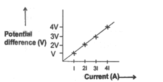
(b) Resistance of a Conductor
The electric current is a flow of electrons through a conductor. When the electrons move from one part of the conductor to the other part, they collide with other electrons and with the atoms and ions present in the body of the conductor. Due to these collisions, there is some obstruction or opposition to the flow of electrons through the conductor.
The property of a conductor due to which it opposes the flow of current through it, is called resistance. The resistance of conductor is numerically equal to the ratio of potential difference across its ends to the current following through it.
Resistance=
(c) Unit of Resistance
The S.I. unit of resistance is ohm, which is denoted by the symbol .
When a potential difference of 1 volt is applied to its ends and a current of 1 ampere flows through it, then resistance f the conductor will be 1 ohm.
(d) Conductors, Resistors and Insulators
On the basis of their electrical resistance, all the substances can be divided into three groups: conductors, resistors and insulators.
(i) Conductors
Those substances which have very low electrical resistance are called conductors. A conductor allows the electricity to flow through it easily. Silver metal is the best conductor of electricity. Copper and aluminum metals are also conductors. Electric wires are made of copper or aluminum because they have very low electrical resistance.
(ii) Resistor
Those substances which have comparatively high electrical resistance, are called resistors. The alloys like nichrome, manganin and constantan (or ureka), all have quite high resistances, so they are used to make those electrical devices where high resistance is required. A resistor reduces the current in the circuit.
(iii) Insulators
Those substances which have infinitely high electrical resistance are called insulators. An insulator does to allow electricity to flow through it. Rubber is an excellent insulator. Electrician wear rubber hundgloves while working with electricity because rubber in an insulator and protects them from electric shocks. Wood is also a good insulator.
(e) Factors affecting the Resistance of a Conductor
Resistance depends upon the following factors :
(i) length of the conductor.
(ii) Area of cross – section of the conductor (or thickness of the conductor).
(iii) Nature of the material of the conductor.
(iv) Temperature of the conductor,
Mathematically : it has been found by experiments that :
(i) The resistance of a given conductor is directly proportional to its length i.e. ……….(i)
(ii) The resistance of a given conductor is inversely proportional to its area of cross-section i.e. ……..(ii)
From (i) and (ii)
………..(iii)
Where (rho) is a constant known as resistively of the material of the conductor. Resistivity is also known as specific resistance.
Dependency of resistance on temperature
If is the resistance of the conductor at 0°C and Rt is the resistance of the conductor at t°C then the relation between and Rt is given by.
Rt = T0 (1+) [Here ]
or
Here, = Coefficient of Resistivity, t= temperature in °C
(r) Resistivity
Resistivity, ………(iv)
By using this formula, we will now obtain the definition of resistivity. Let us take a conductor having a unit area of cross – section of 1 m2 and a unit length of 1 m. So, putting A = 1 and = 1 in equation (iv), we get:
Resistivity, = R
The resistivity of a substance is numerically equal to the resistance of a rod of the substance which is 1 metre long and 1 metre square in cross – section.
The S.I. unit of resistivity is ohm-metre which is written in symbols as – m.
Resistivity of a substance does not depend on its length or thickness. It depends only on the nature of the substance. The resistivity of a substance is its characteristic property. So, we can use the resistivity values to compare the resistances of two or more substances.
(i) Importance of resistivity
A good conductor of electricity should have a low resistivity and a poor conductor of electricity should have a high resistivity. The resistivities of alloys are much more higher than those of the pure metals. It is due to their high resistivities that manganin and constantan alloys are used to make resistance wires used in electronic appliances to reduced the current in an electrical circuit.
Nichrome alloy is used for making the heating elements of electrical appliances like electric irons, room-heaters, water-heaters and toasters etc. because it has very high resistivity and it does not undergo oxidation (or burn) even when red-hot.
(ii) Effect of temperature of resistivity
The resistivity of conductors (like metals) is very low. The resistivity of most of the metals increases with temperature. On the other hand, the resistivity of insulators like ebonite, glass and diamond is very high and does to changes with temperature. The resistivity of semi-conductors like silicon and germanium is in between those of conductors and insulators and decreases on increasing the temperature. Semi-conductors are proving to be of great practical importance because of their marked change in conducting properties with temperature and impurity concentration.
9. COMBINATION OF RESISTANCES (OR RESISTORS )
Apart from potential difference, current in circuit depend or resistance of the circuit. So, in the electrical circuits of radio, television and other similar things, it is usually necessary to combine two or more resistances to get the required current in the circuit. We can combine the resistances lengthwise (called series) or we can put the resistances parallel to one another. Thus, the resistances can be combined in two ways : (i) series combination (ii) parallel combination
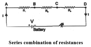
(i) Series combination of resistors
Consider three resistors of resistances R1, R2 and R3 connected in series to cell of potential difference V as shown in figure. Since the three resistors are connected in series therefore the current I through each of them is same.
Then by Ohm’s law the potential drop across each resistor is given by V1 = IR1, V2 and V3 = IR3.
Since V is the total potential in the circuit therefore by conservation of energy we have
V = V1 + V2 + V3
Substituting for V1, V2 and V3 in above equation we have,
V = IR1 + IR2 + IR3 ……….. (i)
If RS is the equivalent resistance of the series combination, then by Ohm’s law we have
V = IRs ……….. (ii)
Therefore from equations (i) and (ii) we have
IRs = IR1 + IR2 + IR3
Hence Rs = R1 + R2 + R3
Thus in series combination the equivalent resistance is the sum of the individual resistances. For more resistors, the above expression would have been- Rs = R1 + R2 + R3 + …………
NOTE :
In a circuit, if the resistors are connected in series :
(A) The current is same in each resistor of the circuit :
(B) The resistance of the combination of resistors is equal to sum of the individual resistors.
(C) The total voltage across the combination is equal to the sum of the voltage drop across the individual resistors.
(D) The equivalent resistance is greater than that of any individual resistance in the series combination.
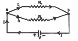
(ii) Parallel combination of resistors
Consider two resistors R1 and R2 connected in parallel as shown in figure. When the current I reached point ‘a’, it splits into two parts I1 going through R1 and I2 going through R2. If R1 is greater than R2, then I1 will be less than I1 i.e. the current will tend to take the path of least resistance.
Since charge must be conserved, therefore the current I that enters point ‘a’ must be equal to the current that leaves that point. Therefore we have I = I1 + I2 …….(i)
Since the resistors are connected in parallel therefore the potential across each must be same, hence by Ohm’s law we have substituting in equation (i)
we have, ……..(ii)
Let RP be the equivalent resistance of the parallel combination, they by Ohm’s law we have, ……..(iii)
Hence from equations (ii) and (iii) we have,
An extension of this analysis to three or more resistors in parallel gives the following general expression
NOTE :
(A) The sum of the reciprocals of the individual resistance is equal to the reciprocal of equivalent resistance, RP.
(B) The currents in various resistors are inversely proportional to the resistances, higher the resistance of a branch, the lower will be the current through it. The total current is the sum of the currents flowing in the different branches.
(C) The voltage across each resistor of a parallel combination is the same and is also equal to the voltage across the whole group considered as unit.
NOTE : For n equal residences
10. HEATING EFECT OF CURRENT
When the ends of a conductor are connected to a battery, then free electrons move with drift velocity and electric current flows through the wire. These electrons collide continuously with the positive ions of the wire an thus the energy taken from the battery is dissipated. To maintain the electric current in the wire, energy is taken continuously from the battery. This energy is transferred to the ions of the wire by the electrons. This increases the thermal motion of the ions, as a result the temperature of the wire rises. The effect of electric current due to which heat is produced in a wire when current is passed through it is called heating effect of current or Joule heating. In 1841 Joule found that when current is passed through a conductor the heat produced across it is :
(i) Directly proportional to the squire of the current through the conductor i.e. H I2
(ii) Directly proportional to the resistance of the conductor i.e. H R
(iii) Directly proportional to the time for which the current is passed i.e. H ∝ t
Combining the above three equations we have H ∝ I2Rt or H=
Where J is called Joule’s mechanical equivalent of heat and has a value of J = 4.18 cal-1. The above equation is called Joule’s law of heating.
In some cases, heating is desirable, while in many cases, much as electric motors, generators or transformers, it is highly undesirable. Some of the devices in which heating effect of an electric current is desirable, are incandescent lamps, toasters, electric irons and stoves. The tungsten filament of an incandescent lamp operates at a temperature of 2700 °C. Here, we see electrical energy being converted into both heat and light energy.
(a) Electric Energy
The fact that conductors offer resistance to the flow of current, means that work must be continuously done to maintain the current. The role of resistance in electrical circuits in analogous to that of friction in mechanics. To calculate the amount of work done by a current I, flowing through a wire of resistance R, during the time t, the amount of work done is given by – W = QV
but as Q = I × t
therefore, the amount of work done, W is
W = V × I × t
By substituting the expression for V from Ohm’s law, V = IR
we finally get W = Rt
This shows that the electrical energy dissipated or consumes depends on the product of the square of the current I. flowing through the resistance R and the time t.
(i) Commercial unit of electrical energy (Kilowatt – hour) :
The S.I. unit of electrical energy is joule and we know that for commercial purposes we use a bigger unit of electrical energy which is called “kilowatt – hour”. One kilowatt – hour is the amount of electrical energy consumed when an electrical appliance having a power rating of 1 kilowatt and is used for 1 hour.
(ii) Relation between kilowatt hour and Joule :
Kilowatt-hour is the energy supplied by a rate of working of 1000 watts for 1 hour.
1 kilowatt-hour = 3600000 joules 1 kWh = 3.3 × 10⁶ J
(b) Electric Power
The rate at which electric energy is dissipated or consumed, is termed as electric power. The power P is given by, P = W/t = I2 R
The unit of electric power is watt, which is the power consumed when 1 A of current flows at a potential difference of 1 V.
(i) Unit of power : The S.I. unit of electric power ‘watt’ which is denoted by the letter W. The power of 1 watt is a rate of working of 1 joule per second.
A bigger unit of electric power is kilowatt.
1 kilowatt (kW) = 1000 watt.
Power of an agent is also expressed in horse power (hp).
1 hp = 746 watt.
(ii) Formula for calculating electric power :
We know, Power, P = and Work, W = V × I × t joules
P =
P = V × I
P = V × I
Power P in timers of I and R :
Now from Ohm’s law we have
V = I × R
P = I × R × I
P = × R
Power P in terms of V and R :
We know, P = V × I
From Ohm’s low I =
P = V ×
P =
(c) Power – Voltage Rating of Electrical Appliances :
Every electrical appliance like an electric bulb, radio or fan has a label or engraved plate on it which tells us the voltage (to be applied) and the electrical power consumed by it. For example, if we look at a particular bulb in our home it may have the figures 220 V, 100W written on it. Now 220 V means that this bulb is to be used on a voltage of 220 volts and 100 W Which means it has a power consumption of 100 watts or 100 joules per second.
(d) Application of Heating Effect of Current
Domestic electric appliances such as electric bulb, electric iron geyser, room heater etc work on heating effect of current and are rated in terms of voltage and wattage. The coils of these devices are made of a material of a very high resistance, (for instance, nichrome or tungsten) such that when a current passes through the coil, heat is generated. Generally the potential difference applied to the electrical appliance is the same as the of the mains i.e. 220-230 V in India an d110 V is U.S.A. Canada etc.
(e) Electric Fuse
An electric fuse in an easily fusible wire of short length put into an electric circuit for protection purpose. It is arranged to melt (“blow”) at a definite current. It is an alloy of lead and tin (37% lead + 63% tin). It has a low resistivity and low melting point. As soon as the safe limit of current exceeds, the fuse “blows” and the electric circuit is cut off.
Consider a wire of length L, radius r and resistivity p. Let I be the current flowing through the wire. Now rate at which heat is produced in the wire.
P = I2 R =
This heat increases the temperature of the wire. Due to radiation some heat is lost. The temperature of the fuse becomes constant when the heat lost due to the radiation becomes equal to the heat produced due to the passage of current. This given the value of current which can safely pass through the fuse. In other words we have,
11. HOUSE – HOLD ELECTRICAL CIRCUIT
Electric power is usually generated at placed which are very far from the place where it is consumed. At the generating station, the electric power is generated at 11.000 volt (because voltage higher than this causes insulation difficulties, while the voltage lower than this involves high current). This voltage is alternating of frequency 50 Hz (i.e. changing its polarity 50 times in a second). The power is transmitted over long distances at high voltage to minimize the loss of energy in the transmission line wires. For a given electric power, the current becomes low at a high voltage and therefore the loss of energy due to heating (=I2 Rt) becomes less. Thus, the alternating voltage is stepped up from 11 kV to 132 kV at the generating station (or called grid sub – station). It is then transmitted to the main sub-station. At the main sub-station, this voltage is stepped down to 33 kV and is transmitted to the switching transformer station or the city sub-station. At the city sub-station, it is further stepped down to 220 V for supply to the consumer as shown in figure.
To supply power to a house either the overhead wires on poles are used or an underground cable is used. Before the electric line is connected to the meter in a house, a fuse of high rating ( 50 A) is connected at the pole or before the meter. This is called the company fuse. The cable used for connection has three wire : (i) live (or phase) wire, (ii) neutral wire and (iii) wire. The neutral and the earth wire are connected together at the local sub-station, so the neutral wire is at the earth potential. After the company fuse, the cable is connected to a kWh meter. From the meter, connections are made to the distribution board through a main fuse and a main switch.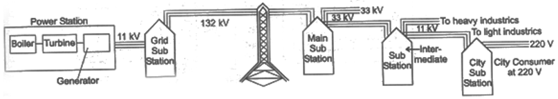
The main switch is a double pole switch. it has iron covering. The covering is earthed. This switch is used to cut the connections of the live as well as the neutral wires simultaneously. The main switch and the meter and locally earthed (in the compound of house). From the distribution board, the wires go to the different parts of the house.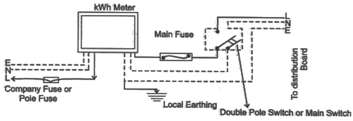
There are two systems of wiring which are in common use :
(i) The tree system (ii) The ring system
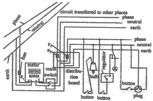
(a) Tree System
In this system different branch lines are taken from the distribution board for the different parts of the house. These branch lines look like the different branches of a tree. Each branch line is taken to a room through a fuse in the live wire. The different circuits are connected in parallel so that if there is a short circuiting in one distribution circuit, its fuse will blow off, without affecting the electric supply in the other circuits. The neutral N and the earth E are common for all circuits. The connection to the neutral N is to complete the circuit. All the appliances in a room are connected in parallel so that they work at the same voltage. The line wires used for connections should be of proper current carrying capacity depending on the rating of the appliance to avoid their overheating. The overheating in line often results in fire. The switches and sockets should also have the proper current carrying capacity.
Disadvantages :
(i) It requires plugs and sockets of different sizes for different current carrying capacities.
(ii) When the fuse in one distribution line blows, it disconnects all the appliances in the distribution line.
(iii) This wiring is expensive.
(iv) If a new appliance is to be installed requiring higher current say 15 A, white the original circuit in the room is for 5 A rating, then it is necessary to put new leads up to the distribution box. This could be quite expensive and inconvenient.
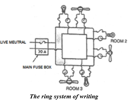
(b) Ring System
The ring-system of electric wiring is now rapidly replacing the older tree system described above. It consists of a ring-circuit. Wires starting from the main fuse-box, run around all the main rooms o the house and then come back to the fuse-box again. The fuse box contains a fuse of rating about 30A. A separate connection is taken from the live wire of the ring for each appliance. The terminal of the appliance is connected to the live wire through a separate fuse and a switch. If the fuse of one appliance burns, it does not affect the other appliances. For each appliance, the wires used for connection should b of proper carrying capacity.
Advantages :
It can be noted that the current can travel to an individual appliance through two separate paths. Thus effectively the connection for each appliance is through double thickness of wire. Therefore the wire used for ring main is of a lower rating than that would be required for a direct connection to the mains. This reduces the cost of wiring considerably. Plugs and sockets of the same size can be used, Another advantage of this system is in installing a new appliance, since a new line up to the distribution box is not required. The appliance can be directly connected to ring main in the room. The only consideration is that the total load on the ring circuit should not exceed the main fuse viz. 30 A.
(c) Domestic Heating Applications
Electric appliances like iron, heater radiator etc. depend on the fact that when a current is sent through a wire, the wire is heated up and it begins to radiate energy.
The most widely used material for making the heater wire is nichrome. It is an alloy of nickel and chromium in the ratio of 4 : 1. It is chosen because of the following reasons :
(i) It has high resistivity. A nichrome wire of ordinary length shows sufficient resistance.
(ii) It can withstand high temperature without oxidation.
(iii) Its melting point is very high.
(d) Hazards of Electricity
We have seen earlier that touching a bare electricity wire with current flowing through it can give a dangerous electric shock. This is because electricity then flows through the body and damages the cells. The among of damage caused depends on the magnitude of current and the duration for which it flows is the body. The magnitude of current increases if the body is wet. That is why we are always advised not to touch any electrical appliances or a switch with wet hands.
A severe electric shock affects the muscles. Sometimes the shock may be so severe than the person may not be able to use his muscle to pull his hand away from the wire. In extreme cases, the heart muscles may get affected and may even lead to death.
EARTHING
Earthling means to connect the metal case of electrical appliance to the earth (at zero potential) by means of a metal wire called “earth wire”. In household circuits, we have three wires, the live wire, the neutral wire and the earth wire. In household circuits. we have three wires, the live wire, the neutral wire and the earth wire. One and of the earth wire is buried the earth. We connect the earth wire to the metal case of the electrical appliance by using a three-pin plug. The mental casing of the appliance will now always remain at the zero potential of the earth. We say that the appliance has been earthed or grounded.
If, by chance, the live wire touches the metal cause of the electric iron (or any other appliance) which has been earthed, then the current passed directly to the earth through the earth wire. It does not need our body to pass the current and therefore, we do not get an electric shock. Actually, a very heavy current flows through the earth wire and the fuse of household wiring blows out or melts. And it cuts off the power supply. In this way, earthing also saves the electrical appliance from damage due to excessive current.
COLOUR CODING OF WIRES
An electric appliance is provided with a three-core flexible cable. The insulation on the three wires is of different colours. The old convention is red for live, black for neutral and green for earth. The new international convention is brown for live, light blue for neutral and green (or yellow) for earth.
GALVANOMETER
A galvanometer is an instrument that can detect the presence of a current is a circuit. The pointer remain at zero (the centre of the scale) for zero current flowing through it. It can deflect either to the left or to the right of the zero mark depending on the direction of current.
(i) Moving coil galvanometer (ii) Moving magnet galvanometer
it is used to make ammeter and voltmeter as follows :
(a) Ammeter
Ammeter is an electrical instrument which measures the strength of current in ‘ampere’ in a circuit which is always connected in series in circuit so that total current (to be measured ) may pass through it. The resistance of an ideal ammeter is zero 9practically it should be minimum).
(b) Voltmeter
it is an electrical instrument which measures the potential difference is ‘volt’ between two points of electric circuit. The only difference between ammeter and voltmeter is that ammeter has its negligible (approximately zero) resistance so that it may measure current of circuit passing through it more accurately giving the deflection accordingly, while the voltmeter passes negligible current through itself so that potential difference developed due to maximum current passing through circuit may be measured.
Voltmeter has very high resistance and the resistance of an ideal voltmeter is infinite.
A voltmeter is always connected in parallel.