


1. INTRODUCTION
Nature has endowed the human eye (retina) with the sensitivity to detect electromagnetic waves within a small range of the electromagnetic spectrum. Electromagnetic radiation belonging to this region of the spectrum (wavelength of about 400 nm to 750 nm) is called light. It is mainly through light and the sense of vision that we know and interpret the world around us.
There are two things that we can intuitively mention about light from common experience. First, that it travels with enormous speed and second, that it travels in a straight line. It took some time for people to realise that the speed of light is finite and measurable. Its presently accepted value in vacuum is c = 2.99792458 × 10⁸ m s–1. For many purposes, it suffices to take c = 3 × 10⁸ ms–1. The speed of light in vacuum is the highest speed attainable in nature.
The intuitive notion that light travels in a straight line seems to contradict that light is an electromagnetic wave of wavelength belonging to the visible part of the spectrum. How to reconcile the two facts? The answer is that the wavelength of light is very small compared to the size of ordinary objects that we encounter commonly (generally of the order of a few cm or larger). In this situation, a light wave can be considered to travel from one point to another, along a straight line joining them. The path is called a ray of light, and a bundle of such rays constitutes a beam of light.
In this chapter, we consider the phenomena of reflection, refraction and dispersion of light, using the ray picture of light. Using the basic laws of reflection and refraction, we shall study the image formation by plane and spherical reflecting and refracting surfaces. We then go on to describe the construction and working of some important optical instruments, including the human eye.
Particle Model Of Light
Newton’s fundamental contributions to mathematics, mechanics, and gravitation often blind us to his deep experimental and theoretical study of light. He made pioneering contributions in the field of optics. He further developed the corpuscular model of light proposed by Descartes. It presumes that light energy is concentrated in tiny particles called corpuscles. He further assumed that corpuscles of light were mass less elastic particles. With his understanding of mechanics, he could come up with a simple model of reflection and refraction. It is a common observation that a ball bouncing from a smooth plane surface obeys the laws of reflection. When this is an elastic collision, the magnitude of the velocity remains the same. As the surface is smooth, there is no force acting parallel to the surface, so the component of momentum in this direction also remains the same. Only the component perpendicular to the surface, i.e., the normal component of the momentum, gets reversed in reflection. Newton argued that smooth surfaces like mirrors reflect the corpuscles in a similar manner.
In order to explain the phenomena of refraction, Newton postulated that the speed of the corpuscles was greater in water or glass than in air. However, later on it was discovered that the speed of light is less in water or glass than in air.
In the field of optics, Newton – the experimenter, was greater than Newton – the theorist. He himself observed many phenomena, which were difficult to understand in terms of particle nature of light. For example, the colours observed due to a thin film of oil on water. Property of partial reflection of light is yet another such example. Everyone who has looked into the water in a pond sees image of the face in it, but also sees the bottom of the pond. Newton argued that some of the corpuscles, which fall on the water, get reflected and some get transmitted. But what property could distinguish these two kinds of corpuscles? Newton had to postulate some kind of unpredictable, chance phenomenon, which decided whether an individual corpuscle would be reflected or not. In explaining other phenomena, however, the corpuscles were presumed to behave as if they are identical. Such a dilemma does not occur in the wave picture of light. An incoming wave can be divided into two weaker waves at the boundary between air and water.
2. REFLECTION
When a beam of light is incident on a surface, a part of it is returned back into the same medium. The part of light which is returned back into the same medium is called the reflected light.
The remaining part of light is absorbed if the surface on which the incident light strikes is opaque or it is partly transmitted and partly absorbed if the surface is transparent.
Reflection
The bouncing back of light into the same medium after striking a surface is called reflection.
Reflection of light is the process which enables us to see different objects around us. Luminous bodies are directly seen, but non luminous objects are seen only because they reflect the light incident on them which on entering into our eyes, make them visible.
Types Of Reflections
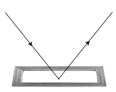
The phenomenon due to which a parallel beam of light travelling through a certain medium, on striking some smooth polished surface, bounces off from it, as parallel beam, in some other direction is called regular reflection.
Regular reflection takes place from the objects like looking glass, still water, oil, highly polished metals, etc.
Regular reflection is useful in the formation of images, e.g., we can see our face in a mirror only on account of regular reflection. However, it causes a very strong glare in our eyes.
Irregular Reflection or Diffused Reflection
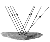
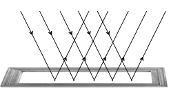
The phenomenon due to which a parallel beam of light, travelling through some medium, gets reflected in various possible directions, on striking some rough surface is called irregular reflection or diffused reflection.
The reflection which takes places from ground; walls; trees; suspended particles in air; and a variety of other objects, which are not very smooth, is irregular reflection.
Irregular reflection helps in spreading light energy over a vast region and also decreases its intensity. Thus, it helps in the general illumination of places and helps us to see things around us.
Laws Of Reflection
1. The incident ray, the reflected ray and the normal lie in the same plane, at the point of incidence.
2. The angle of incidence is always equal to the angle of reflection.
Note:
(i) The angle of deviation for a ray incident on a plane mirror is calculated as follows:
d =180 – 2i (or) 180 – 2r where i = angle of incidence, r = angle of reflection
(ii) Glancing of angle (g) is the angle made either by the incident ray or the reflected ray with the mirror.
g = 90 – i (or) 90 – r or d/2, where d = angle of deviation.
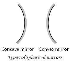
3. SPHERICAL MIRRORS
A spherical mirror whose reflecting surface is curved inwards is called a concave mirror. A spherical mirror whose reflecting surface is curved outwards is called a convex mirror.
i) The centre of the reflecting surface of a spherical mirror is a point, called the pole. It is represented by the letter P.
ii) The reflecting surface of a spherical mirror forms a part of a sphere. This sphere has a centre. This point is called the centre of curvature of the spherical mirror. It is represented by the letter C.
iii) The radius of the sphere of which the reflecting surface of a spherical mirror forms a part, is called the radius of curvature of the mirror. It is represented by the letter R.
iv) Imagine a straight line passing through the pole and the centre of curvature of a spherical mirror.
v) The point of the principal axis where the parallel beam of light meets after reflection is called principal focus. It is represented by F.
vi) The distance between the principal focus (F) and pole of the mirror (P) is called focal length. It is represented by f.]
vii)The diameter of the reflecting surface of spherical mirror is called its aperture. In the Figure, distance MN represents the aperture.
Note: R = 2f
4. IMAGES FORMATION BY SPHERICAL MIRRORS
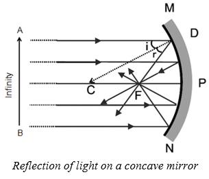
Reflection Of Light By Spherical Mirror
The reflection of light by a spherical mirror takes place according to certain definite rules as follows.
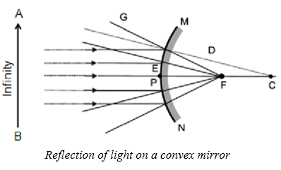
(i) A ray parallel to the principal axis, after reflection, will pass through principal focus in case of a concave mirror or appear to diverge from the principal focus in case of a convex mirror.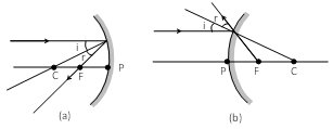
(ii) A ray passing through the principal focus of a concave mirror or a ray directed towards the principal focus of a convex mirror, after reflection, will emerge parallel to the principal axis.
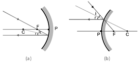
(iii) A ray passing through the centre of curvature of a concave mirror or directed in the direction of the centre of curvature of a convex mirror, after reflection, is reflected back along the same path.
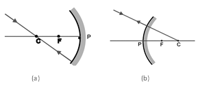
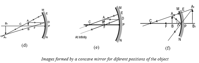
Image Formation By Concave Mirror
How about the images formed by spherical mirrors? How can we locate the image formed by a concave mirror for different positions of the object? Are the images real or virtual? Are the images enlarged, diminished or have the same size? The nature, position and size of the image formed by a concave mirror depend on the position of the object in relation to point P, F and C. The image formed is real for some positions of the object. It is found to be a virtual image for a certain other position. The image is either magnified, reduced or has the same size, depending on the position of the object. We can study the formation of image by spherical mirrors by drawing ray diagrams. To construct the ray diagrams, it is more convenient to consider only two rays.
These rays are so chosen that it is easy to know their directions after reflection from the mirror. You may take any two of the rays mentioned in the previous section for locating the image. The intersections of the two reflected rays give the position of image of the point object. The images formed for different positions of the object are shown in Figure (a to f).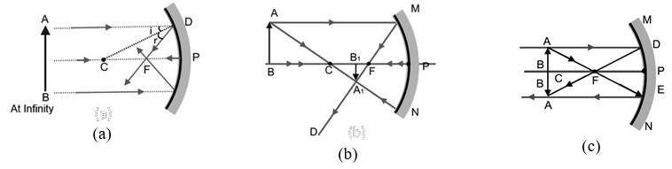
 POSITION AND NATURE OF IMAGES FORMED FOR DIFFERENT POSITIONS OF THE OBJECT FOR A CONCAVE MIRROR
|
Position of the object |
Position of the image |
Relative size of the image |
Nature of the image |
|
At infinity |
At focus (F) |
Highly diminished |
Real and inverted |
|
Beyond C |
Between C and F |
Diminished |
Real and inverted |
|
At C |
At C |
Same size |
Real and inverted |
|
Between C and F |
Beyond C |
Enlarged |
Real and inverted |
|
At F |
At infinity |
Highly magnified |
Real and inverted |
|
Between F and P |
On the other side of the mirror. |
Enlarged |
Virtual and erect |
Image Formation By A Convex Mirror
We consider two positions of the object for studying the image formed by a convex mirror. First is when the object is at infinity and the second position is when the object is at a finite distance from the mirror. The ray diagrams for the formation of image by a convex mirror for these two positions of the object are shown in the Figure.
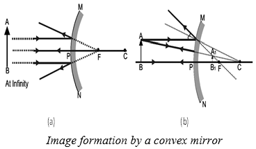
IMAGE FORMATION BY A CONVEX MIRROR FOR DIFFERENT POSITIONS OF THE OBJECT
|
Position of the object |
Position of the image |
Relative size of the image |
Nature of the image |
|
At infinity |
At focus (F) |
Highly diminished |
Virtual and erect |
|
Between infinity and pole of the mirror |
Between F and P |
Diminished |
Virtual and erect |
Uses Of Spherical Mirrors
I. Uses of concave mirror
Concave mirrors are commonly used in torches, search-lights and vehicles head lights to get powerful parallel beams of light. They are used as shaving mirrors to see a lager image of the face. The dentists use concave mirrors to see large images of the teeth of patients. Large concave mirrors are used to concentrate sun light to produce heat in solar furnaces.
II. Uses of convex mirrors
Convex mirrors are commonly used as rear-view mirrors in vehicles. These mirrors are fitted on the sides of the vehicle, enabling the driver to see traffic behind him/her to facilitate safe driving. Convex mirrors are preferred because they always give an erect image. Also they have a wider field of view as they are curved outwards.
5. NEW CARTESIAN SIGN CONVENTIONS
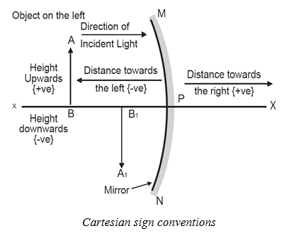
While dealing with the reflection of light by spherical mirrors, we shall follow a set of sign conventions called the New Cartesian Sign Convention. In this convention, the pole (P) of the mirror is taken as the origin. The principal axis of the mirror is taken as the X axis ( X) of the coordinate system. The conventions are as follows.
(i) The object is always placed to the left of the mirror.
(ii) All distances parallel to the principal axis are measured from the pole of the mirror.
(iii) All the distances measured to the right of the origin (along +X-axis) are taken as positive while those measured to the left of the origin (along -X-axis) are taken as negative.
(iv) Distances measured perpendicular to and above the principal axis (along +Y-axis) are taken as positive.
(v) Distances measured perpendicular to and below the principal axis (along -Y-axis) are taken as negative
The New Cartesian Sign Convention described above is illustrated in the following Figure.
These sign conventions are applied to obtain the mirror formula
CONCLUSIONS FROM THE SIGN CONVENTION
|
For concave mirror |
For convex mirror |
||
|
Distance of the object |
u is negative |
Distance of the object |
u is negative |
|
Distance of the real image |
v is negative |
Distance of the virtual image |
v is negative |
|
Distance of the virtual image |
v is positive |
Focal length |
f is positive |
|
Focal length |
f is negative |
Radius of curvature |
R is negative |
|
Radius of curvature |
R is negative |
Height of the object |
O is positive |
|
Height of the object |
O is positive |
Height of the inverted (erect) image |
I is positive |
|
Height of the inverted (real) image |
I is positive |
|
|
|
Height of the erect (virtual) image |
I is positive |
||
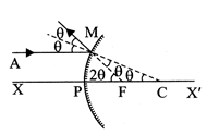
6. RELATION BETWEEN FOCAL LENGTH AND RADIUS OF CURVATURE
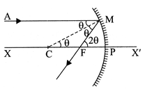
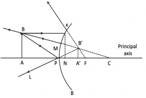
Consider a ray of light AM parallel to the principal axis and striking the mirror at M. It is reflected along MF. At M, the angle of reflection is equal to the angle of incidence .
Now, PFM = 2
[ Exterior angle is the sum of interior opposite angles]
Since the mirror under consideration has a small aperture therefore the angle q is small and the arc PM may be regarded as a straight line perpendicular to the principal axis X’X.
Now,
The angles (in radian) are so small that tan and tan 2 can be replaced by and 2 respectively.
Radius of curvature = 2 × focal length
7. MIRROR FORMULA OR MIRROR EQUATION
The equation relating the object distance, the image distance and focal length of the mirror is called the mirror formula.
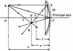
Let an object AB is placed at a distance u from the concave mirror and its real inverted image from at a distance from it. C is centre of curvature of mirror.
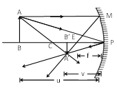
Let PB = u
PB’ = v
PF = f
CP = R = 2f
ABC is similar to A’B’C
______________ (i)
Also, A’B’P’ is similar to ABP
_____________ (ii)
Comparing equation (i) and (ii), we get
uv uR = vR uv
2uv = 4R + vR
Dividing by uvR
R = 2f
Note:
The Above formula is used for any type of image formed by concave and convex mirrors.
8. LINEAR MAGNIFICATION OF SPHERICAL MIRRORS
The ratio of the size of the image, as formed by reflection from the mirror to the size of the object, is called linear magnification produced by the mirror. It is represented by the symbol m. If I be the size of the image and O be the size of the object,
then m =
If we represent size of the object by and size of the image by then, I = and O =
Hence, m=
Expression
(i) For concave mirror forming real image
I = A’ B’ = – (inverted image),
O = AB = + (erect object)
then,
In similar s A’ B’ P and ABP
Then, i.e.
(ii) For convex mirror forming virtual image
I = A’ B’ = + (erect image)
O = AB = + (erect object)
Then,
In similar triangles, A’B’P and ABP.
Then, i.e.
It is same as for a concave mirror.
Hence, we conclude that, the linear magnification produced by a mirror is equal to the ratio of the image distance to the object distance with a minus sign.
Note: For a real image u and v, both are negative, hence m is negative.
For a virtual image u is negative, v is positive, hence m is positive.
Areal Magnification
It is the ratio of the area of the image to the area of the object. It is also called superficial or surface magnification.
Areal magnification =