


9. REFRACTION OF LIGHT
We know that light travels in a straight line path. This is true as long as the light rays are travelling in the same medium having the same optical density throughout. If, however, the light rays are made to go from one transparent medium, to another transparent medium, they change their direction (or bend) at the boundary separating two media. For example, when light rays travelling in air go into another medium say glass, they change their direction (or bend) on entering the glass medium.
The bending of the ray of light when it travels from one medium to another is called refraction of light.
Optically Rarer Medium And Optically Denser Medium
A transparent substance in which light travels is known as a medium. Air, glass, water, alcohol, etc. are all examples of different media. Different media are said to have different optical densities. The speed of light depends on the optical density of the medium. Therefore, light travels with different speeds in different media having different optical densities. For example, the speed of light in air is 3 × 10⁸ m/s, whereas that in glass is 2 × 10⁸ m/s and in water, it is 2.25 × 10⁸ m/s. It is clear from these values that the speed of light is more in air but less in water and least in glass. A medium in which the speed of light is more is known as an optically rarer medium. Air is an optically rarer medium as compared to glass and water. A medium in which the speed of light is less is known as an optically denser medium. Glass is an optically denser medium than air and water. Consider once again the speed of light in air, water and glass. The speed of light in water (2.25 × 10⁸m/s) is less than that in air (3 × 10⁸ m/s) but more than that in glass (2 × 10⁸ m/s). So, water is optically denser than air, but it is optically rarer than glass.
Optical Density Versus Mass Density
Do not get confused with optical density and mass density. Both are different from each other. While mass density is the ratio of mass per unit volume of a substance, optical density is the ratio of speed of light in one medium to another. For example, turpentine is optically denser than water as it has a greater refracting effect on light, but has a lower mass density than water.
Cause For Refraction Of Light
When a ray of light changes its medium, the basic change that occurs is the change in its wavelength. This change in the wavelength leads to the change in its velocity and the change velocity is responsible for its deviation; and hence, refraction takes place.
Types Of Deviations
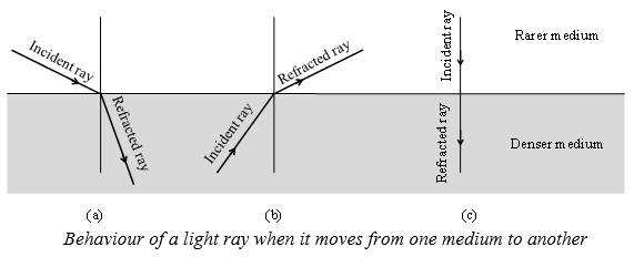
1. When a ray of light travels from a rarer medium to a denser medium (Figure a), it bends towards the normal.
2. When a ray of light travels from a denser medium to a rarer medium (Figure b), it bends away from the normal.
3. If the incident ray falls normally (or perpendicularly) (Figure c) on the surface of a glass slab, then there is no bending of the ray of light and it goes straight.
Since the incident ray goes along the normal to the surface, the angle of incidence in this case is zero (0°) and the angle of refraction is also zero (0°),
i.e.
Note:
1. When light travels from one medium to another, the frequency of light does not change. However, the velocity and the wavelength of light change.
2. When a ray of light passes from rarer to denser medium it bends towards the normal and .
Angle of deviation, d = i r
3. When a ray of light passes from denser to rarer medium, it bends away from the normal and .
Angle of deviation d = r – i
4. A ray of light travelling along the normal passes undeflected.
Terms Related To Refraction
i)Transparent surface
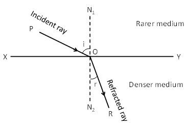
The plane surface which refracts light is called transparent surface. In diagram XY is the section of a plane transparent surface.
ii) Point of incidence
The point on transparent surface, where the ray of light meets it, is called point of incidence. In diagram Q is the point of incidence.
iii) Normal
Perpendicular drawn on the transparent surface at the point of incidence is called normal. In diagram, N1 QN2 is the normal on surface XY.
iv) Incident ray
The ray of light which strikes the transparent surface at the point of incidence is called incident ray. In diagram, PQ is the incident ray.
v) Refracted ray
The ray of light which travels from the point of incidence into the other medium is called refracted ray. In diagram, QR is the refracted ray.
vi) Angle of incidence
The angle between the incident ray and the normal on the transparent surface at the point of incidence is called the angle of incidence. It is represented by the symbol i. In diagram, angle PQN1 is the angle of incidence.
vii) Angle of refraction:
The angle between the refracted ray and the normal on the transparent surface at the point of incidence is called angle of refraction. It is represented by the symbol r. In diagram angle RQN2 is the angle of refraction.
Laws Of Refraction
(i) The incident ray, the refracted ray and the normal to the interface of two transparent media at the point of incidence, all lie in the same plane.
(ii) The ratio of sine of angle of incidence to the sine of angle of refraction is a constant, for the light of a given colour and for the given pair of media. This law is also known as Snell’s law of refraction.
If i is the angle of incidence and r is the angle of refraction, then,
This constant value is called the refractive index ( or n) of the second medium with respect to the first.
10.REFRACTIVE INDEX
We know that a ray of light travels obliquely from one transparent medium into another will change its direction in the second medium. The extent of the change in direction that takes place in a given pair of media is expressed in terms of the refractive index of the second medium with respect to the first medium. The refractive index can be linked to the relative speed of propagation of light in different media.
Light propagates with different speeds in different media. It travels the fastest in vacuum with the highest speed of 3 × 10⁸ ms–1. Its speed reduces considerably in glass. Consider a ray of light travelling from medium 1 into medium 2. Let i, r be the angle of incidence and angle of refraction.
The refractive index of the second medium with respect to the first medium is given by
If medium 1 is air or vacuum, then 12 is called Absolute refractive index () of medium 2.
Absolute refractive index of a medium is the ratio to the speed of light in vacuum to the speed of light in medium.
Relative Refractive Index
If v1 and v2 are the speeds of light in media of refractive indices and respectively, then
Relative refractive index of medium 2 with respect to medium 1 is the ratio of the speed of the light in medium 1 to the speed of light medium 2.
Note: Refractive index of medium 2 with respect to 1 is also represented as
CONCLUSION:
For a given wavelength and given pair of substances, the ratio of the sine of the angle of incidence to the sine of the angle of refraction is a constant.
KNOW MORE
As light goes from rarer to denser medium, its wavelength decreases.
Red light ( = 7800Å) enters glass ( = 1.5) from air and becomes green light ( = 5200 Å)
During refraction, the velocity and wavelength of light change.
11. PRINCIPLE OF REVERSIBILITY OF PATH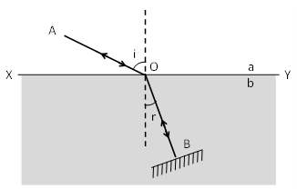
If a ray of light, after suffering any number of reflections or refractions has its path reversed at any stage, it travels back to the source along the same path in the opposite direction. This is called principle of reversibility.
Consider an interface XY which separates a rarer medium ‘a’ from a denser medium ‘b’.
Let a ray of light AO be incident on the interface as shown in figure. At an angle of incidence i. After refraction, the ray follows the path OB such that r is the angle of refraction.
If a plane mirror is placed normal to the path of the refracted ray, then the ray is reversed and retraces the whole path in the opposite direction.
Let us now make use of the principle of reversibility of light to arrive at an important result. When ray of light travels from rarer to denser medium, the refractive index of denser medium with respect to rarer medium is given by
When the path angle of light is reversed, then r will be treated as angle of incidence and i will be treated as angle of refraction because the ray of light would now travel from denser to rarer medium. So, refractive index of rarer medium with respect to denser medium is given by …(2)
Multiplying (1) by (2), we get
(or)
Conclusion: The refractive index of denser medium with respect to rarer medium is the reciprocal of the refractive index of rarer medium with respect to denser medium.
If the refractive index of glass with respect to air is , then the refractive index of air with respect to glass is .
12. REFRACTION THROUGH A PARALLEL SLAB
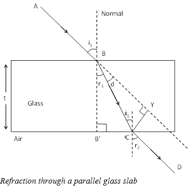
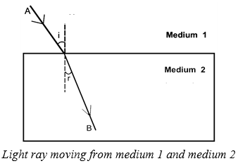
Consider a ray of light AB passing from air (medium 1)through a parallel sided glass slab (medium 2) into air (medium 1). The ray of light will clearly suffer two refractions. Since the medium on both sides of glass is the same therefore, the ray of light will get laterally shifted without any deviation (Figure). This is proved below.
Air to Glass : ––––––– (1)
Glass to Air : ––––––– (2)
Multiplying (1) and (2),
we get,
But we know,
Since the slab is parallel sided ⇒ i2 = r1.
Conclusion :
The ray of light will leave the slab at an angle which it entered the glass slab on the opposite side. However, it gets lateral displacement (i.e., A ray of light incident obliquely on a parallel sided glass slab emerges out parallel to the incident ray).
Lateral Shift Or Lateral Displacement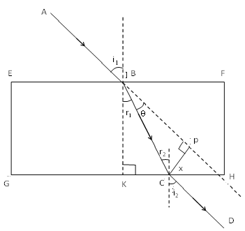
Consider a parallel sided slab EFGH as shown in Figure such that EF is parallel to GH. A light ray AB passing from air through a parallel sided glass slab undergoing refraction and then entering the air again. The refracted and emergent ray are respectively BC and CD. The ray under goes refraction twice, one at the surface EF and other at the surface GH.
I1 and r1 be the angle of incidence and angle of refraction at the face EF.
From Snell’s law, …….(1)
i2,r2 are the angle of incidence and angle of refraction at face GH.
From Snell’s law, ……(2)
but r1 = r2, so ……..(3)
from (1) and (3) equations we get i1 = i2.
The emergent ray is laterally displaced with respect to the incident ray. The displacement depends upon the angle of incidence, the refractive index and the thickness of the slab. The perpendicular distance CP between the emergent ray and the direction of the incident ray is called lateral shift.
Let the thickness of the slab be t.
i.e. EG = BK = t.
From right angled triangle BCP, sin , CP = BC sin where = i1 – r1
From right angled triangle BKC, ;
CP = BC sin
As i1 = =i and r1 – =r
Lateral displacement can be given as: x =
Put sin(i – r)=sin i cos r-cos i sin r .
We get x = t
In the approximation of small angle of incidence i with sin i= i and cos i= 1
Lateral displacement is given as
13. SPHERICAL LENSES
A transparent material bound by two surfaces, of which one or both surfaces are spherical, forms a lens.
This means that a lens is bound by at least one spherical surface. In such spherical lenses, the other surface would be plane. A lens may have two spherical surfaces, bulging outwards. Such a lens is called a double convex lens. It is simply called a convex lens. It is thicker at the middle as compared to the edges. Convex lens converges light rays. Hence it is called converging lens.
Similarly, a double concave lens is bounded by two spherical surfaces, curved inwards. It is thicker at the edges than at the middle. Such lenses diverge light rays and are called diverging lenses. A double concave lens is simply called a concave lens.
Terms Related To Lenses
i) A lens has two spherical surfaces. Each of these surfaces forms a part of a sphere.
ii) The centers of these spheres are called centres of curvature of the lens. The centre of curvature of a lens is usually represented by the letter C. Since there are two centre’s of curvature, we may represent them as C1 and C2.
iii) An imaginary straight line passing through the two centres of the curvature of a lens is called its principal axis.
iv) The central point of a lens is called its optical centre. It is represented by the letter O. A ray of light through the optical centre of a lens passes without suffering any deviation.
v) The effective diameter of the circular outline of a spherical lens is called its aperture. Lenses whose aperture is much less than its radius of curvature are called thin lenses with small aperture.
vi) Several rays of light parallel to the principal axis are falling on a convex lens. These rays after refraction from the lens are converging to a point on the principal axis. This point is called the principal focus of the lens.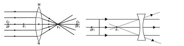
Several rays of light parallel to the principal axis are falling on a concave lens. These rays after refraction from the lens, are appearing to diverge from a point on the principal axis. This point is called the principal focus of the concave lens.
If you pass parallel rays from the opposite surface of the lens, you will get another principal focus on the opposite side. Letter F is usually used to represent principal focus. However, a lens has two principal foci. They are represented by F1 and F2.
vii) The distance of the principal focus from the optical centre of a lens is called its focal length. The letter f is used to represent the focal length.
KNOW MORE
First Principal Focus And First Focal Length
First principal focus of al lens is that p oint on the principal axis of the lens at which if an object is placed, the image would be formed at infifinity. It is dentoted F1.
The distance of the first principal focus of a lens from its optical centre is called the first focal lenth of the lens. It is denoted f1.
Second Principal Focus And Second Focal Length
Second principal focus of a lens is that point on the principal axis of the lens where the image formed when the object is at infinity. It is denoted by F2.
The distance of the second principal focus of a lens from its optical centre is called the second principal focal length of the lens. It is denoted f2.
14. IMAGE FORMATION BY LENSES
We can represent image formation by lenses using ray diagrams. Ray diagrams will also help us to study the nature, position and relative size of the image formed by the lenses. For drawing ray diagrams in lenses, we consider any two of the following rays.
(i) A ray of light from the object, parallel to the principal axis, after refraction from a convex lens, passes through the principal focus on the other side of the lens, as shown in Figure (a). In case of a concave lens, the ray appears to diverge from the principal focus located on the same side of the lens, as shown in Figure (b)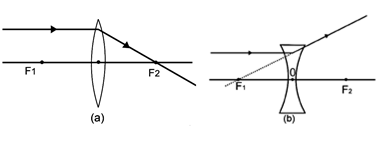
(ii) A ray of light passing through a principal focus after refraction from a convex lens will emerge parallel to the principal axis. This is shown in Figure (a) below. A ray of light appearing to meet at the principal focus of a concave lens, after refraction, will emerge parallel to the principal axis. This is shown in Figure (b) below.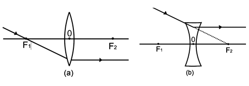
(iii) A ray of light passing through the optical centre of a lens will emerge without any deviation. This is illustrated in Figure (a) and (b) below.
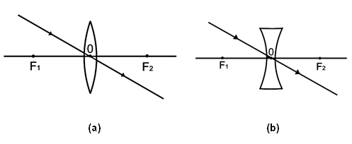
Image Formation By A Convex Lens
Case I:
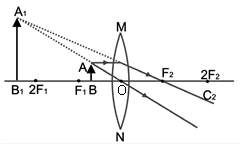
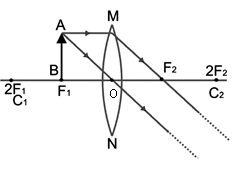
Image formed by a convex lens when the object is placed between the optical centre and the principal focus (object between O and F1)
Characteristics of the image formed.
1. The image is virtual.
2. The image is erect.
3. The image is enlarged (or magnified).
4. The image is formed on the same side of the lens, behind the object.
Applications
When the object is placed between the optical centre of the convex lens and the principal focus, an erect and magnified image is formed. It is used as a magnifying glass (or simple microscope) in the following cases:
1. It is used by the palmists to study the lines of the palm.
2. It is used for seeing clearly the weave patterns of the cloth.
3. It is used as reading glass to read the fine print (like letters).
4. It is used to study biological specimens such as parts of the flower, etc.
Case II:
When the object is placed at the focus of a convex lens (object at F1)
Characteristics of the image formed
1. The image is real.
2. The image is inverted.
3. The image is highly enlarged (or magnified).
4. The image is formed at infinity, on the other side of the lens.
Applications
The above case is used in making searchlights and spotlights in theatres. In a searchlight, a powerful lamp is placed at the principal focus of a convex lens, which produces a powerful parallel beam of light.
Case III:
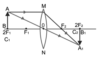
When the object is placed between F1 and 2F1.
Characteristics of the image formed
1. The image is real.
2. The image is inverted.
3. The image is enlarged (or magnified).
4. The image is formed beyond 2F2, on the other side of the lens.
Applications
This type of image formation is used in film and slide projectors, when enlarged image of a small slide (or film) is formed on a screen.
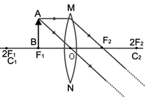
Case IV:
When the object is at 2F1
Characteristics of the image formed
1. The image is real.
2. The image is inverted.
3. The image is of the same size as the object.
4. The image is formed at 2F2, on the other side of the lens.
Applications
This type of image formation is used in terrestrial telescope, for erecting the inverted image formed by the objective lens of the telescope.
Case V: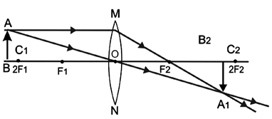
When the object is beyond 2F1
Characteristics of the image formed
1. The image is real.
2. The image is inverted.
3. The image is diminished (i.e. smaller than the object).
4. The image is formed between F2 and 2F2, on the other side of the lens.
Applications
This type of image formation is used in a photographic camera, where a small, real and inverted image of an object is formed on the film.
Case VI:
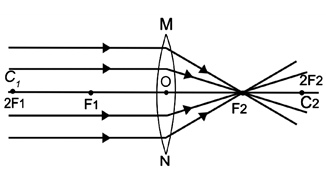
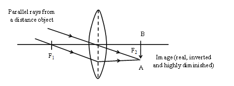
When the object is at infinity (such that the rays coming from it are parallel to the principal axis of the convex lens)
Characteristics of the image formed
1. The image is real.
2. The image is inverted.
3. The image is diminished to a point (highly diminished).
4. The image is formed at F2, on the other side of the lens.
Applications
This type of image formation is used in a burning glass. When the rays of the sun are focussed by the lens of the burning glass on a piece of paper, the paper catches fire. The lens of the burning glass focuses the heat radiations on the paper as a result of which, the temperature of the paper rises to its ignition temperature and it catches fire.
Case VII:
When the object is at infinity (such that the rays coming from it are not parallel to the principal axis of the convex lens)
Characteristics of the image formed
1. The image is real.
2. The image is inverted.
3. The image is highly diminished.
4. The image is formed on the focal plane on the other side of the lens.
Applications
This type of image formation is used for an objective lens in a telescope. It forms small, inverted image of far off objects in the focal plane in front of the eye lens.
IMAGES FORMED BY A CONVEX LENS FOR VARIOUS POSITIONS OF THE OBJECT
|
Position of the object |
Position of the image |
Relative size of the image |
Nature of the image |
|
At infinity |
At focus F |
Highly diminished, point-sized |
Real and inverted |
|
Beyond 2F |
Between F and 2F |
Diminished |
Real and inverted |
|
At 2F |
At 2F |
Same size |
Real and inverted |
|
Between F and 2F |
Beyond 2F |
Enlarged |
Real and inverted |
|
At focus F |
At infinity |
Infinitely large of highly enlarged |
Real and inverted |
|
Between focus F and optical centre O |
On the same side of the lens as the object |
Enlarged |
Virtual and erect |
Images Formed By A Concave Lens
Case I :
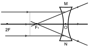
When the object is located at infinity (such that the rays coming from it are parallel to the principal axis)
Characteristics of the image formed
1. The image is virtual.
2. The image is erect.
3. The image is highly diminished to a point size.
4. The image is formed at ; on the same side of the lens as the object.
Case II:
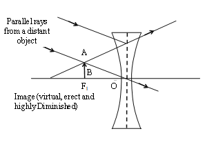
When the object is located at infinity [such that the parallel rays from it are falling obliquely (not parallel) to the principal axis
Characteristics of the image formed
1. The image is virtual.
2. The image is erect.
3. The image is highly diminished.
4. The image is formed in the focal plane on the same side of the lens as the object.
Applications
This type of image formation is used in Galilean telescope, where concave lens acts as an eye lens.
Case III:
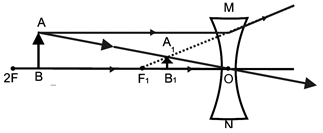
When the object is anywhere between the optical centre (O) and infinity.
Characteristics of the image formed
1. The image is virtual.
2. The image is erect.
3. The image is diminished.
4. The image is formed between the optical centre (O) and the principal focus (F1) on the same side of the lens.
Applications
This type of image formation is used mainly in spectacles for the correction of shortsightedness or myopia.
IMAGES FORMED BY A CONCAVE LENS FOR VARIOUS POSITIONS OF THE OBJECT
|
Position of the object |
Position of the image |
Size of the image |
Nature of the image |
|
At infinity |
At focus F |
Highly diminished point-sized |
Virtual and erect |
|
Between infinity and optical center O of the lens |
Between focus F and optical center O |
Diminished |
Virtual and erect |
15. LENS FORMULA
The equation relating the object distance, the image distance and the focal length, is called the lens formula.
Power of lens is P = (f in metre) = (f in cm)
S.I unit of Power is dioptre.
Magnification Produced By Lenses
The size of the image formed by a lens depends on the position of the object from the lens. For example, we have seen that if the object is placed beyond , the image formed by a convex lens is diminished and if the object is placed between and the optical centre, an enlarged image is formed. The linear magnification is the ratio of the height of the image to the height of the object i.e.,
Magnification=
If the magnification ‘m’ has a positive value, the image is virtual and erect. On the other hand, if the magnification ‘m’ has a negative value, the image is real and inverted. Now, areal magnification of lens is
Note: For mirrors, . It is so because for an inverted image v is negative in case of mirrors while it is positive in case of lenses.
Cartesian Sign Conventions For Lenses
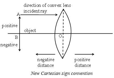
According to the New Cartesian Sign Convention:
1. Object should be taken on the left side to the lens.
2. All distances are measured from the optical centre of the lenses.
3. The distances measured in the direction of the incident light are taken as positive whereas the distances measured against the direction of the incident light are taken as negative.
4. The distances measured upwards and perpendicular to the principal axis is taken as positive whereas the distances measured downwards and perpendicular to the principal axis is taken as negative.
On the basis of the New Cartesian Sign Convention, the focal length of a convex lens is considered as power is also given the same sign as focal length positive and the focal length of a concave lens is considered as negative.
Power Of A Lens
When a beam of light passes through a lens, it gets deviated from its path. A lens which can produce more deviation is said to be of more power.
The power of a lens is a measure of deviation produced in the path of rays, passing through it.
A lens of short focal length deviates the rays more, while a lens of large focal length deviates the rays less. Hence, power of a lens is expressed (or measured) in terms of the reciprocal of focal length.
Power of a lens is defined as the reciprocal of the focal length of the lens, expressed in metre.
Let f = focal length of the lens
power power
Unit of the power of a lens:
The S.I unit of the power of a lens is dioptre, which is denoted by the letter D.
Note:
1. One dioptre is the power of a lens whose focal length is one metre.
2. The power of a lens can be measured directly by using an instrument called dioptremetre. It is used by opticians to measure the power of spectacle lenses.
3. A convex lens has a positive focal length. So, the power of a convex lens is considered to be positive and is written as +D. A concave lens has a negative focal length, so the power of a concave lens is considered to be negative and is denoted as –D.
Power Of A Combination Of Lenses
If a number of lenses are placed in close contact with each other, then the power of the combination of lens is equal to the algebraic sum of the powers of individual lenses. Thus, if two lenses of powers P1 and P2 are placed in contact with each other, then their resultant power P is given by the algebraic sum of the individual powers P1 and P2 of the two lenses.
i.e., P = P1 + P2
For example: If a convex lens of power +5 D and a concave lens of power –12D are placed in contact with each other, then their resultant power will be,
P = P1 + P2 P = +5D + (–12) D
P = 5D – 12D P = –7D
This shows that a combination of a convex lens of power +5D and a concave lens of power –12D has a resultant power of –7D. So, this combination of convex lens and concave lens behaves like a concave lens (of power –7D).
In optical instruments like camera, microscopes, telescopes, etc. a number of a lenses are combined together to increase the sharpness of the image.