


1. INTRODUCTION
We use electricity for many purposes to make our tasks easier. For example, we us electricity to operate pumps that lift water from wells or from ground level to the roof top tank. We also use of electricity for lighting. Electricity makes it possible to light our homes, roads, offices, markets and factories even after sunset. This helps us to continue working at night. A power station provides us with electricity. However, the supply of electricity may fail or it may not be available at some places. In such situations, a torch is sometimes used for providing light. A torch has a bulb that lights up when it is switched on. Have you ever thought from where does the torch get electricity from?
2. ELECTRIC CHARGE
In nature there are two types of charges. They are positive and negative charges.
• Electric charges can exist independently either as positive or negative charges.
• A positively charged body has more positive charges and negatively charged body has more negative charges.
• A neutral body has equal amounts of positive and negative charges.
• Positive charge is denoted by +q and negative charge is denoted by -q.
• The S.I unit of Charge is Coulomb.
• Static electricity is study of electric charges at rest.
3. ELECTRIC CURRENT
Flow of charge in unit time is known as Electric Current. It is represented by ‘i’.
• Electric Current ‘i’ = q/t; where ‘q’ is charge; ‘t’ is time.
• Unit: S.I unit of electric current is Ampere.
• Electric current has Electrical Energy.
• Electrical energy comes from electric cells.
• Electric current in our homes come from electrical generators or from power houses.
• In electric cells, current flows from positive terminal to negative through a metal wire.
• Electricity travels along a medium. It is generally a metal wire coated with plastic or rubber.
4. ELECTRIC CELL
Electricity to the bulb in a torch is provided by the electric cell. Electric cells are also used in alarm clocks, wristwatches, transistor radios, cameras and many other devices. An electric cell has a small metal cap on one side and a metal disc on the other side.
It has a positive (+) sign and a negative (–) sign marked. The metal cap is the positive terminal of the electric cell.
The metal disc is the negative terminal. All electric cells have two terminals; a positive terminal and a negative terminal. An electric cell produces electricity from the chemicals stored inside it. When the chemicals in the electric cell are used up, the electric cell stops producing electricity. The electric cell then has to be replaced with a new one.
A torch bulb has an outer case of glass that is fixed on a metallic base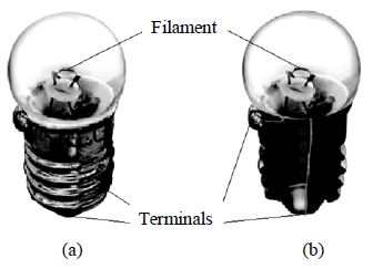
The thin wire that gives off light is called the filament of the bulb. The filament is fixed to two thicker wires, which also provide support to it. . One of these thick wires is connected to the metal case at the base of the bulb. The other thick wire is connected to the metal tip at the centre of the base. The base of the bulb and the metal tip of the base are the two terminals of the bulb. These two terminals are fixed in such a way that they do not touch each other. The electric bulbs used at home also have a similar design. Thus, both the electric cell and the bulb have two terminals each.
Battery: A combination of two or more cells is called a battery.
Button Cells: It is also a dry cells but are small in size and are used in calculators, wrist watches, etc.
Storage Cells: A car battery or batteries being used in buses & trucks are combination of 6 or more cells inside. They can be recharged with the help of an electric charger & used again and again. For this purpose these batteries are also called accumulators.
5. POWER HOUSES
• For producing a large amount of electrical energy, big power houses are constructed. In these energy of flowing water or the energy of steam is converted into electrical energy.
• Energy generated in power houses is carried by electric cables to the cities and villages.
• When electric supply fails due to some reason, then electric generators provide electric current. In these diesel engine rotates the dynamo and converts the mechanical energy into electric energy.
Solar Cell: Solar cells are specially designed cells having solar panels.
• Solar panels collect solar energy from sun and converts this solar energy into electrical energy.
• This energy is used either directly or stored in an accumulator.
Working of Torchlight: The source of energy for the torch are the electric cells inside the torch.
• Small torches are with a single cell inside, while most torches have two or more cells.
• When switched on , the metal strip inside the torch moves ahead and it touches the base of the reflector which holds the bulb. As soon as it makes contact with the reflector, the circuit is completed and the bulb lights up.
• When switched off, the metal strip is pulled back. The contact of metal strip with the reflector is broken i.e., circuit is broken.
6. ELECTRIC CIRCUIT
An electric cell or dry cell is the source of energy for the bulb to glow and warm up. Let us now learn the way in which this electric energy is made available to the bulb in the torch.
Making of a simple Electric Circuit
Step 1
Take out the bulb from bulb from a torch. Examine the bulb carefully.
The bulb is a small globe of thin glass enclosing a coiled filament supported on two thick wires. One of these thick wires is connected to the metal casing around the base of the bulb. The other wire is connected to the metal tip at the base. The metal casing and the metal tip at the base are the two terminals of the bulb.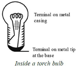
Step 2
Take two pieces of insulated wire. Insulated wires have metal wire inside with a plastic covering on the outside. Remove the plastic covering from both the ends of each piece of wire. Fix these wires on the bulb as shown in the figure with the help of Insulating adhesive tape. Or fix the bulb on a bulb holder. The two screws on the bulb holder are the two terminals which are connected to the two terminals on the bulb. The two pieces of wire be connected to the two terminals on the holder, as shown in the picture.
Step 3
Connect the two free ends of the wires from the bulb or the bulb holder to an electric cell in such a way that one piece of wire is connected to the positive terminals of the cell and the other to the negative terminal of the cell. This may be done with the help of a rubber band or an adhesive tape.
When you have finished with connections, the bulb lights up.
With your finger trace the path of the electricity from the positive ( + ve) terminal on the cell to the negative (–ve) terminal of the cell. It is a roundabout path travelled by electricity.
Closed and Open Circuit
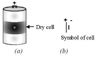
The dry cell has two terminals. The central terminal of the dry cell is called positive terminal. The base of the dry cell (which is made of a metal) is called negative terminal.
The above figure (a) shows the terminals of dry cell. The figure (b) shows the symbol for dry cell.
The long line represents positive terminal of the cell and the small and thick line represents negative terminal of the cell.
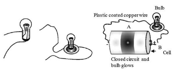
For this experiment you need a torch cell; a torch bulb marked 1.5 V, cellotape, a plastic coated 1 metre long copper wire and an old used blade.
Cut the plastic coated copper wire into two halves A and B. Remove plastic coating from each end of the wire such that 1 cm of plastic is removed. Now fix one bare end of each wire A and B to the terminals of 1.5 V bulb with the cellotape. Fix the other end of wire A to the base of cell with the help of cellotape. Now touch the bare end of wire B to the central terminal of cell as shown in figure. What do you observe?
The bulb lights up. This shows that electric current is flowing in wire A and B through the bulb.
The path along which electric current flows is called electric circuit.
Now remove the wire B from the central terminal as shown in Fig. . What do you observe? The bulb does not glow. It is because electric current does not flow, if the path is broken or path is incomplete.
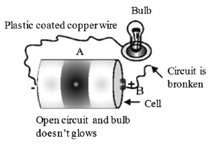
Closed Circuit or Complete Circuit
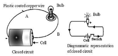
When the path which starts from one terminal of the cell, ends at the other terminal of the cell, without any break, then such a circuit is called complete circuit or closed circuit. When the circuit is closed, then any electric appliance in that circuit starts working. In the present case the bulb starts glowing.
Open Circuit or Incomplete Circuit
When the path of current, starting from one terminal of the cell to another terminal of the cell is broken or incomplete, then such a circuit is called open circuit or incomplete circuit.
For example, when we remove wire B from central terminal of cell, then the circuit is open circuit or incomplete circuit.
Switches are used in the household wiring^ to open or close the electric circuit. When we switch on a particular electric appliance, we close the electric circuit.
Conversely, when we switch off an electric appliance, we open the electric circuit.
7. SYMBOLS USED IN ELECTRICAL CIRCUITS
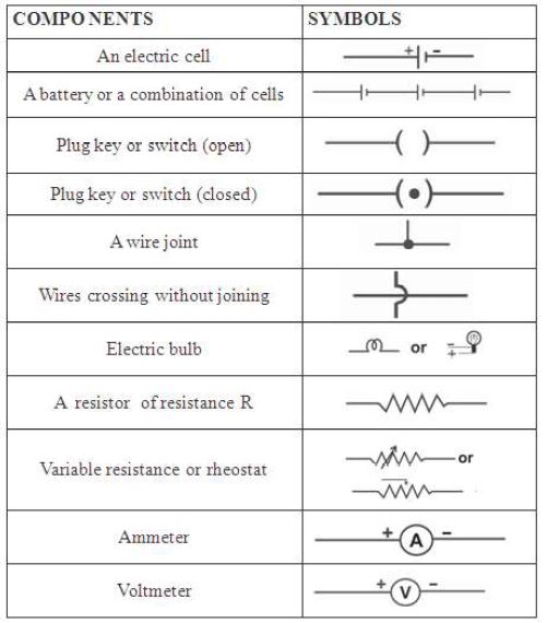
A switch, a simple device to ‘close’ or ‘open’ a circuit: An electric circuit passes through a switch. Switch is a simple device which helps us to close or open the circuit. It helps in saving electricity when not in use. You are always advised to switch ‘off the lights or other gadgets in your home to save electricity.
Ammeter is used to measure the current and voltmeter is used to measure the potential difference.
More details of ammeter and shall be learnt is voltmeter higher classes.
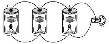
8. CONNECTING ELECTRIC CELLS IN SERIES
Take a dry cell and a torch bulb. Connect the bulb to the cell using copper wires as shown in Fig. .
Observe the intensity- of light. The bulb does not glow brightly.
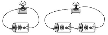
Now take one more dry-cell and connect two cells as shown in figure. In this method the positive of the first cell is connected to the negative of the second. The negative of the first and the positive of the second are connected to the bulb. The bulb now glows brighter.
In the battery torch or battery light two or three dry cells are put into a metal container in series. The positive of one cell is connected to the negative pole of another cell in the series connection, When the, switch is turned on, the circuit is closed and the bulb glows and gives light.
Connecting Electric Cells in Parallel
Take three dry cells and connect them as shown in fig.. That is all the positive poles of the three cells are connected together, and all the three negative poles are connected together.
These three positives and three negatives are connected to the bulb- You will observe that there is no change in the brightness of the bulb!
When cells are connected in parallel, their total electromotive force is the same as that if any one of them.
When cells are connected in series, their electromotive force is equal to the sum of the EMF of all the cells used.
Connect three torch bulbs in series as shown in figure. Connect this to a dry cell and observe that brightness of each of the three bulbs. Now connect one more dry cell in series with he first cell.
Observe the brightness of each of the bulb. Then connect one more dry cell in series with the first two cells. Again observe the bulbs.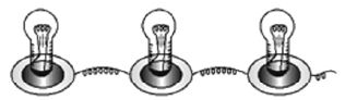
Disconnect one of the three bulbs in the circuit. The circuit becomes open and all the three bulbs stop glowing. In series connection of bulbs,’ if one bulb gets fused, all the other bulbs in the series will stop working. Three bulbs connected in Series
9. CONNECTING BULBS IN PARALLEL
Connect three bulbs in parallel. That is, one end of each of the three bulbs are connected one wire, the other ends of the three bulbs are connected to another wire! These two wires are connected to a dry cell. All the three bulbs glow dimly. Now disconnect one of the bulbs. The other bulbs continue to glow as before.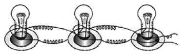
To study the properties of (i) Series circuit, (ii) Parallel circuit
Materials required : a battery of four cells two bulbs of 1 watt each one fused bulb a switch few lengths of connecting wires cellotape.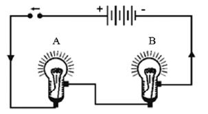
Method: Connect the bulbs A and B in series by connecting them to connecting wires with the help of cellotape as shown above. Connect the free ends of connecting wires to a battery through a switch. Close the switch. What do you observe? Both the bulbs will glow. However, they will not glow very brightly. Open the switch. What do you observe?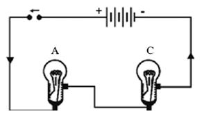
Both the bulbs will stop glowing.
Now remove the bulb B and instead fix a fused bulb C as in the above figure. What is your observation?
Bulb A does not glow.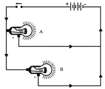
Following are the conclusions from the above investigation
1. In series circuit all the appliances work simultaneously when switch is closed. Conversely, all appliances stop working when switch is open.
2. In series circuit, if any, of the appliances goes out of order, the other appliances stop working.
3. As the bulbs were not glowing very brightly, it can be concluded that in series the appliances do not work to their full capacity.
Now connect the bulbs A and B in parallel, such that they have common positive and common negative terminals as illustrated by Fig. , through a switch and a battery.
Close the switch. What do you observe? Both the bulbs A and B glow very brightly. Now remove the bulb B and instead fix a fused bulb C Fig. . What is your observation?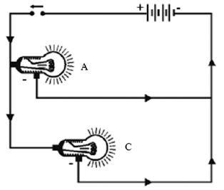
The bulb A continues glowing brightly, whereas bulb C does not glow. Following conclusions can be drawn from above investigation.
1. In parallel circuit all the appliances work independently
2. In parallel circuit if one appliance goes out of order, the other continues working. It means that each appliance in parallel circuit can be operated independently by a switch.
3. As the bulbs glow brightly, it means each appliance gets enough electric energy, and hence, works to its full capacity.
10. CONDUCTORS AND INSULATORS
The materials which allow the electric current to pass through them are the conductors of electricity and the materials through which electric current does not pass are the non-conductors or the bad conductors of electricity. Metals are the conductors of electricity. Non metals like glass, plastic, wood, paper, cloth and rubber are the non-conductors of electricity.
Non-conductors of electricity are also called insulators. All leads (wires) being used in an electric circuit are metallic wires coated with plastic or rubber. Coating of a conductor with a non-conductor is called insulation.
If we happen to touch a metallic end of a lead through which current is passing, it gives an electric ‘SHOCK’. The shock may be fatal too or otherwise it shakes the body and harms the person who has suffered the electric shock. Insulation saves a person from electric shock.