


1. LIGHT
If we enter a dark room, objects present there are not visible. However, if a bulb is switched on, everything in the room becomes visible. It shows that for vision the presence of light is essential.
Definition of light: It is an invisible energy which causes in us sensation of sight (vision). Since light is obtained from heat energy, i.e., when an object is heated to a temperature beyond [C, we can say that light is a kind of energy].
It must be kept in mind that light energy makes the surrounding objects visible, but by itself it is an invisible energy.
For example, if we are seeing a coloured poster, then we are seeing only the poster and not the coloured lights reflected fronts it. It is because light is invisible. The various colours reflected from the poster excite the retina of the eye, which in turn sends a message to the brain. It is the brain which finally makes out the colours of the poster. Thus, we can conclude that light is an invisible energy which causes in us sensation of vision.
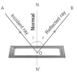
2. REFLECTION OF LIGHT
When a beam of light is incident on a surface, a part of it is returned back into the same medium. The part of light which is returned back into the same medium is called the reflected light. The remaining part of light is absorbed if the surface on which the incident light strikes is opaque or it is partly transmitted and partly absorbed if the surface is transparent.
Reflection
The return of light into the same medium after striking a surface is called reflection. Reflection of light is the process which enables us to see different objects around us. Luminous bodies are directly seen, but non luminous objects are seen only because they reflect the light incident on them which on entering into our eyes, make them visible.
Note: Reflection is possible in case of plane mirror. A plane mirror is a plane glass plate which is silvered at its one surface. The other surface is then reflecting surface of the plane mirror.
Types of Reflections
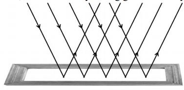
(a) Regular Reflection
The phenomenon due to which a parallel beam of light travelling through a certain medium, on striking some smooth polished surface, bounces off from it, as parallel beam, in some other direction is called
Regular Reflection.
Regular reflection takes place from the objects like looking glass, still water, oil, highly polished metals, etc.
Regular reflection is useful in the formation of images, e.g., we can see our face in a mirror only on account of regular reflection. However, it causes a very strong glare in our eyes.
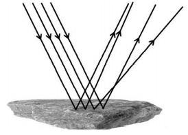
(b) Irregular Reflection or Diffused Reflection
The phenomenon due to which a parallel beam of light, travelling through some medium, gets reflected in various possible directions, on striking some rough surface is called Irregular Reflection or Diffused Reflection.
The reflection which takes places from ground; walls; trees; suspended particles in air; and a variety of other objects, which are not very smooth, is irregular reflection.
Irregular reflection helps in spreading light energy over a vast region and also decreases its intensity. Thus, it helps in the general illumination of places and helps us to see things around us.
3. GENERAL TERMS TO THE REFLECTION
(a) Mirror : A smooth polished surface from which regular reflection can take place is called mirror. MM| is the mirror as shown in figure.
(b) Incident Ray : A ray of light which travels towards the mirror is called incident ray. AB is an incident ray in the figure.
(c) Point of Incidence : The point on the mirror, where an incident ray strikes is called point of incidence. ‘B’ is the point of incidence in the figure.
(d) Reflected Ray : A ray of light which bounces off the surface of a mirror, is called reflected ray. BC is reflected ray in the figure.
(e) Normal: The perpendicular drawn at the point of incidence, to the surface of mirror is called normal. BN is the normal in the figure.
(f) Angle of Incidence : The angle made by the incident ray with the normal is called angle of incidence. ABN is the angle of incidence in the figure.
(g) Angle of Reflection : The angle made by the reflected ray with the normal is called angle of reflection. CBN is the angle of reflection in the figure.
(h) Glance Angle of Incidence : The angle which the incident ray makes with the mirror is called glance angle of incidence. MBA is the glance angle of incidence in the figure.
(i) Glance Angle of Reflection : The angle which the reflected ray makes with the mirror is called glance angle of reflection. M’BC is the glance angle of reflection in the figure.
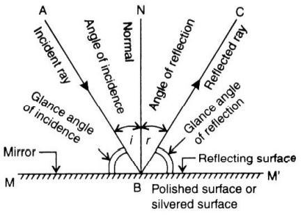
LAWS OF REFLECTION
1. The incident ray, the reflected ray and the normal lie in the same plane, at the point of incidence.
2. The angle of incidence is always equal to the angle of reflection.
Formula for the angle of deviation due to Reflection
In the figure angle of incidence = i; Angle of deviation = d
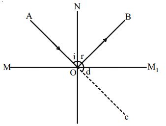
Consider the straight line AOC, i + r +d = 180°
i.e., the sum of angle of incidence, angle of reflection and angle of deviation is 180°.
Therefore, for an angle of incidence i, the angle of deviation is equal to
Note: The deviation produced by n reflections from two plane mirrors inclined at an angle is given by , if n = 2 where n is even.
5. IMAGE
When the rays of light, diverging from an object point, after reflection or refraction, either actually meet at some other point, or appear to meet at some other point, then that point is called image of that object.
Types of images
|
Virtual image |
Real image |
|
1. The rays of light after reflection or refraction appear to meet at some other point. |
The rays of light after reflection or refraction actually meet at some point. |
|
2. It cannot be caught on the screen. |
It can be caught on the screen. |
|
3. It is always erect. |
It is always real. |
|
4. Image of our face in plane mirror is a virtual image. |
Image for med on a cinema screen is a real image. |
GEOMETRICAL CONSTRUCTION OF AN IMAGE OF AN EXTENDED OBJECT IN
A PLANE MIRROR: (TWO-RAY DIAGRAM)
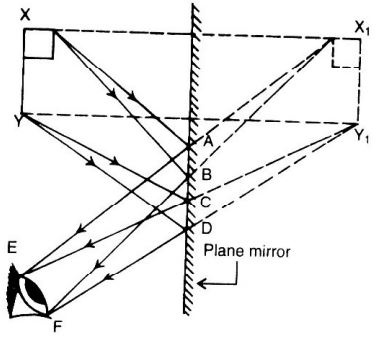
Consider an extended object P situated in front of a plane mirror. For geometrical construction, we will consider two points X and Y on this object. First of all we will locate the position of the image, keeping in mind that image formed in a plane mirror is as far behind as the object is in front of it, by taking normal incidence.
In order to construct two-ray diagram, from point X| draw two rays straight towards eye along X|E and X|F, cutting the mirror at A and B respectively. Join XA and XB to form incident beam on mirror. Similarly, from point Y’ draw two rays towards the eye along Y’E and Y’F cutting at C and D. Join YC and YD to form incident beam on mirror.
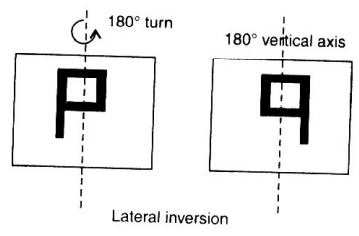
Lateral Inversion
The phenomenon clue to which the image of an object turns through an angle of 180″ through vertical axis rather than horizontal axis, such that right side of image appears as left or vice versa is called lateral inversion.
Characteristics of an Image formed by a Plane Mirror
1. The image is formed behind the mirror and has the same size as the object
2. The image is inverted laterally.
3. The image is as far behind the mirror as the object is in front of it.
4. The image is virtual. It cannot be received on a screen.
5. The image is erected w.r.t object
7. APPLICATIONS OF REFLECTION
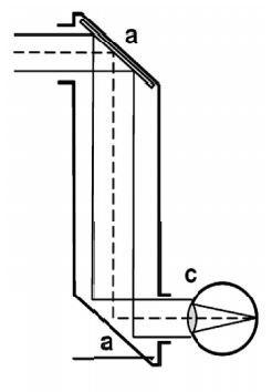
(i) Periscope:
A periscope is an instrument for observation from a concealed position. In its simplest form it consists of a tube with mirrors at each end set parallel to each other at a 45-degree angle. This form of periscope, with the addition of two simple lenses, served for observation purposes in the trenches during World War I
Construction
It consists of a cardboard or wooden tube bent twice at right angles and is provided with two openings. Two plane mirrors (a) are fixed at the bends of the tube at an angle 45°. Both the mirrors face each other. The tube is completely blackened from inside to avoid and reflection from its sides. The parallel rays coming from an object strike the first plane mirror at an angle of 45°. The rays get reflected at an angle of 45°. These reflected rays strike the second mirror and further reflected through an angle of 45°. Thus we can see the image.
Uses
1. It is used to see above the head of crowds.
2. It is used by soldiers in trench warfare.
Disadvantages
1.The final image is not brightly illuminated as light energy is absorbed due to tow successive reflections.
2.Any deposition of moisture or dust on the mirror reduces the reflection almost to nil and hence the periscope cannot be used in places where there is a lot of dust or moisture.
(ii) Kaleidoscope
(Kaleido = beautiful + edos = image + scope = viewing).
It is an instrument used to view beautiful images formed by the reflection of the two or more mirrors (usually three) when placed at different angles.
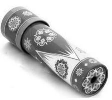
Principle: Multiple reflections take place in plane mirrors. This is the principle of ‘Kaleidoscope’.
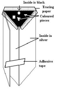
Construction:
Cut out a 16 × 16 cm piece of cardboard. Use a pencil to divide the cardboard into 4 strips each 4 cm wide. Use a sharp knife to score along the pencil lines so that the cardboard can be easily folded into 4 strips. Use paste to attach aluminium foil over 2 of the strips at one end. Colour the next strip black. Fold the strips to make a tube with a triangular cross-section. Two of the inside walls of the triangular tube have aluminium foil on them and the
inside of the third wall is black. Use adhesive tape to keep the folded cardboard in shape. Attach clear plastic to each end of the triangular tube. Put coloured beads or small coloured shapes on the clear plastic at one end. Make a lid out of tracing paper to cover the beads or coloured shapes. The lid must be high enough to let the beads or shapes them move about. Look through the clear plastic at the other end of the triangular tube which is now a kaleidoscope. Turn the kaleidoscope while looking through it a see the changing patterns .formed by light bouncing off the aluminium foil.
A better kaleidoscope can be made if you can use small mirrors instead of aluminium foil. The kaleidoscope was invented by Sir David Brewster (1781-1868).
Uses
1. Kaleidoscope is used as a toy for children.
2. Kaleidoscope is used by costume – designers in cloth mills and fashion designing institutes.
8. PLANE MIRROR – ITS USES
1. They are used as looking glass.
2. They are used by opticians to provide false dimensions.
These false dimension can be obtained when two mirrors are fixed parallel to each other.
3. They are used in the construction of reflecting periscope.
4. They are used in solar cookers for reflecting the rays of sun into the cooker.
5. They are used for signaling purposes.
6. They are used by barbers to show the customer the back of his head.
9. SPHERICAL MIRRORS
Raj and Laxmi were waiting for their dinner. Raj lifted a stainless steel plate and saw his image in it. Oh! This plate acts as a plane mirror. My image is erect and is of the same size. Laxmi saw her image using the back of a steel spoon. “Raj look here! I can also see my erect image though it is smaller in size. This spoon also acts as a mirror of some kind”, said Laxmi. You can also use a spoon or any curved shining surface to see your image. Now try to do these activities on your own.
Activity -1
Take a stainless steel spoon. Bring the outer side of the spoon near your face and look into it.

Do you see your image in it ? Is this image different from what you see in a plane mirror? Is this image erect? Is the size of the image the same, smaller or larger? Now look at your image using the inner side of the spoon.
This time you may find that your image is erect and larger in size. If you increase the distance of the spoon from your face, you may see your image inverted . You can also compare the image of your pen or pencil instead of your face.
Understanding
The curved shining surface of a spoon acts as a mirror. The most common example of a curved mirror is a spherical mirror. Let’s understand something more about these spherical mirrors.
A highly polished plane surface is called a plane mirror. A mirror in which the reflecting surface is curved is called a spherical mirror.
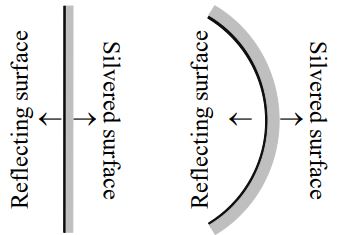
In spherical mirrors the polished reflecting surface is a part of a hollow sphere of glass. Depending upon the nature of the reflecting surface of the mirror, spherical mirrors are of two types.
Different types of spherical mirrors
Concave mirror: A spherical mirror whose inner hollow surface is the reflecting surface is called a concave mirror.
Convex mirror: A spherical mirror whose outer surface is the reflecting surface is called a convex mirror.

10. TERMS RELATED TO SPHERICAL MIRRORS
Aperture: The width (distance) of the spherical mirror from which reflection can take place is called its aperture. It is denoted by MM’
Pole: The centre of a spherical mirror is called its pole. It is denoted by P.
Centre of Curvature: The geometric centre of the hollow sphere of which the spherical mirror is a part is called the centre of curvature of the spherical mirror. It is denoted by C.
Radius of Curvature: The radius of the hollow sphere of which the spherical mirror is a part is called the radius of curvature of the spherical mirror.
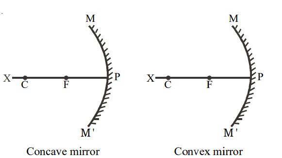
In other words, the distance between the pole and centre of curvature of the spherical mirror (PC) is called its radius of curvature. It is denoted by r.
Principal axis: The straight line passing through the centre of curvature and the pole of a spherical mirror is called its principal axis (PX).
Focus: If a beam of light parallel to the principal axis falls on a concave mirror, all the rays after reflection meet at a point. This point is called the focus (F) of the concave mirror.
If a beam of light parallel to the principal axis falls on a convex mirror, all the rays after reflection diverge. If the reflected rays are extended backwards, they appear to come from a point on the principal axis. This point is called the focus of the convex mirror.
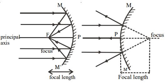
Focal Length: The distance between the pole (P) and focus (F) is called the focal length (f). Denoted by f.
Types of Images formed by Spherical Mirrors
A concave mirror forms both real and virtual images. The size and nature of the image formed by a concave mirror depends on the position of the object. A convex mirror forms only virtual, erect and diminished images. The different types of images formed by a concave mirror as follows.
|
Position of the object |
Position of the image |
Relative size of the image |
Nature of the image |
|
At infinity |
At focus (F) |
Highly diminished |
Real and inverted |
|
Beyond C |
Between C and F |
Diminished |
Real and inverted |
|
At C |
At C |
Same size |
Real and inverted |
|
Between C and F |
Beyond C |
Enlarged |
Real and inverted |
|
At F |
At infinity |
Highly magnified |
Real and inverted |
|
Between F and P |
On the other side of the mirror. |
Enlarged |
Virtual and erect |
11. USES OF SPHERICAL MIRRORS
I Uses of Concave Mirror
Concave mirrors are commonly used in torches, search-lights and vehicles head lights to get powerful parallel beams of light. They are used as shaving mirrors to see a lager image of the face. The dentists use concave mirrors to see large images of the teeth of patients. Large concave mirrors are used to concentrate sun light to produce heat in solar furnaces.
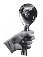
II. Uses of Convex Mirrors
Convex mirrors are commonly used as rear-view mirrors in vehicles. These mirrors are fitted on the sides of the vehicle, enabling the driver to see traffic behind him/her to facilitate safe driving. Convex mirrors are preferred because they always give an erect image. Also they have a wider field of view as they are curved outwards.
12. IMAGES FORMED BY LENS
What is a Lens?
A lens is a piece of glass or any transparent material bound with two surfaces, atleast one of which is a curved surface. The curved surface is spherical (part of a sphere) in nature. Based on the shape of the curve on the surface of a lens, lenses are grouped into two main types:
(i) A convex lens, having a bulge in the centre and with narrow edges.
(ii) A concave lens, having a depression in the centre and thick at the edges.
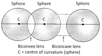
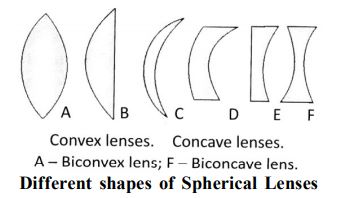
Formation of Spherical Lenses different Shapes of Spherical Lenses
A. Double convex (both the sides convex)
B. Plano convex (converging lens)
C. Concavo convex (convex meniscus)
D. Convexo concave (concave meniscus)
E. Plano concave (diverging lens)
F. Double concave (both the sides concave)
We call these lenses as glasses or specs (short for a pair of spectacles) which are used by people with poor sight to watch things through them. These are nothing but a pair of lenses made from transparent glass and fixed to a frame which is held on to the eyes. A lens, which is a magnifying glass, is used by watchmakers to see very small parts of the machine as big (large) through them.
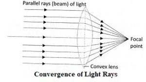
Convex Lens
A convex lens makes the object magnified, when viewed through it. A convex lens is thick in the middle and thin at its edge. When light rays pass through a convex lens, they bend inwards and converge at a common point to form an image of the source of light.
Rays from the sun converge to form its image as a bright spot. A convex lens converges light rays.
Therefore, it is also called a converging lens. The image formed when the object is placed close to a convex lens is virtual, erect and magnified. Virtual images cannot be caught on a screen. Images that are caught on a screen are called real images. When the object is placed at a distance from a convex lens, the image formed is real, inverted and diminished.
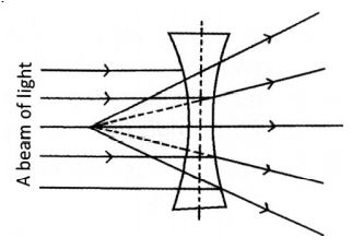
Concave Lens
It is a lens that possesses at least one surface that curves inwards. When light rays are incident on a concave lens, they bend outwards or diverge. The rays diverge away from each other. Thus, a concave lens is also called a diverging lens. A concave lens is thinner at its centre than at its edges, and is used to correct short sightedness. It does not focus at a single point. The image formed by a concave lens is upright, virtual and smaller than the object. For example, the images seen through a peephole are different from normal holes, because these peep holes contain concave lenses.
Applications of Lenses
Lenses are used in magnifying glasses, peep holes, cameras, bioscopes, binoculars, telescopes, microscopes and projectors. A refracting telescope uses a concave mirror and a convex lens.
13. SUNLIGHT
A band of colours extending from violet to red is a rainbow. A rainbow is formed by the refraction and reflection of the sun’s rays through raindrops.
Rainbow
A band of colours extending from violet to red is a rainbow. A rainbow is formed by the refraction and reflection of the sun’s rays through raindrops. When it is raining in one part of the sky and sunny in another, a rainbow appears. The centre of the rainbows arc is always directed away from the sun. It is believed that in the past, Norsemen saw rainbows as bridges for gods to come to the earth from their home in the sky. Norsemen were the inhabitants of Norway. A rainbow lasted for about 9 hours on 14th March, 1994, at a place called Wether by in Yorkshire, England. Although sunlight appears white, it is composed of seven colours. The colours in a rainbow are the colours of sunlight. A rotating disc has a
pencil that serves as a rotator. The disc is covered with violet, indigo, blue, green, yellow, orange and red coloured papers
When the disc is rotated, it appears white instead of the individual colours. This is because a mixture of colours of the rainbow in proper proportions produces white colour. The colours of a rainbow can be represented by the acronym: VIBGYOR: V – Violet, I – Indigo, B – Blue, G – Green, Y – Yellow, O – Orange and R – Red.
Dispersion of Light through a Prism
Take a glass prism. Allow a narrow beam of sunlight to pass through a small hole in the window of a dark room to fall on one face of the prism. The light bends when it passes through the prism. Now allow the light coming out of the other face of the prism to fall on a white sheet of paper or a white wall. Different component colours of white light bend differently, and so the constituent colours can be seen separately. Thus, the colours are said to have dispersed after passing through the prism.