


1. INTRODUCTION
In 600 B.C. a great scientist ‘Thales’ observed that when amber was rubbed with wool, it acquired a strange property of attracting tiny bits of paper, cork or dry straw towards itself.
Later in 16th century ‘Gilbert’ observed the same phenomena in some other substances. Such as ebonite & cat’s skin; glass and silk; sealing wax and wool, etc. He named it as electricity.
The source of all electricity and electrical phenomena is Charge.
2. ELECTRIC CHARGE
In nature there are two types of charges. They are positive and negative charges.
• Electric charges can exist independently either as positive or negative charges.
• A positively charged body has more positive charges and negatively charged body has more negative charges.
• A neutral body has equal amounts of positive and negative charges.
• Positive charge is denoted by +q and negative charge is denoted by -q.
• Unit: S.I unit of Charge is Coulomb.
• Static electricity is study of electric charges at rest.
3. ELECTRIC CURRENT
The rate of flow of charge in a circuit is called electric current. In other words, it is the amount of charge flowing per second. It is denoted by the letter I.
If Q is the charge which is flowing through a conductor in time t, then current is given by
Unit of Current
The S.I unit of current is ampere and it is denoted by the letter ‘A’.
The S.I unit of Q is coulomb and that of t is second.
Thus, the S.I unit of electric current is
Definition of Ampere
When a charge of coulomb flows through a conductor in one second, then the current flowing through the conductor is said to be one ampere.
Thus, when 1 coulomb of charge flows through a conductor in 1 second, then the current flowing through it is said to be 1 ampere.
Smaller units of Electric Current
Sometimes smaller units of current are also used. These are microampere and milliampere.
1 microampere =
1 milliampere =
Bigger unit of electric current:
Sometimes the magnitude of the current flowing in a conductor is very large. This large magnitude of current is expressed in bigger units, such as kilo ampere and mega ampere.
1 kilo ampere (kA) = 1000 A = A
1 mega ampere (MA) = 1,000,000 A = A.
Flow of Current
In metals, the moving charges are the electrons constituting the current, while in electrolytes and ionized gases, electrons and positively charged ions are the ions moving charges which constitute current.
The charge on an electron is negative and is coulomb (symbol C).
Therefore, IC charge is carried by electrons. Hence if I A current flows through a conductor, it implies that electrons pass in 1 second across the cross section of the conductor.
The direction of current is conventionally taken opposite to the direction of motion of electrons.
If n electrons pass through a cross section of a conductor in time t, then total charge passed
Q = n × e and current in conductor
Instrument by which current measured: Current is measured by an instrument called ammeter.
4. ELECTRIC POTENTIAL & POTENTIAL DIFFERENCE
a) We define the electric potential difference between two points in an electric circuit carrying some current as the work done to move a unit charge from one point to the other.
Potential difference (V) between two points
b) The S.I unit of potential difference is volt(V).
One volt is the potential difference between two points in a current carrying conductor when 1 joule of work is done to move a charge of 1 coulomb from one point to the other. The potential difference is measured by means of an instrument called voltmeter.
5. SOURCES OF ELECTRICITY
Electrical energy available to us from electric power houses, domestic generators, batteries, dry cells, button cells.
• Dry cell is the most handy source of electricity which is used in torchlights, watches, clocks.
• We make use of button cells in wrist watches, calculators.
• A combination of two or more cells is called a battery.
• A car battery or batteries used in cars or trucks are combination of ‘six’ or more cells.
These batteries once exhausted can be recharged with the help of an electric changer and used again and again. Hence these are called accumulators.
6. EFFECTS OF ELECTRICITY
Electricity is a form of energy, which help us with
• Heating Effect
• Light Effect
• Magnetic Effect
• Chemical Effect
Heating Effect
Here electrical energy is converted into heat energy.
• Heating effect of electric current in a wire is used in appliances like electric iron, electric kettle, geyser, immersion rod, room heater etc.
• Some metals like silver, copper, aluminium are very good conductors of electricity.
• They offer no obstruction (resistance) to the flow of electricity through them.
• In case of an alloy of nickel and chromium (nichrome – an alloy), electric current does not flow easily and it finds obstruction (resistance). This results in heating of the wire.
• Similarly filament (very thin wire) made from a metal called ‘tungsten’ offers great obstruction to the flow of the electric current through it. Thus an electric work is done in overcoming this friction.
This result in loss of energy. This lost energy appears in the form heat energy and light energy. On passing current through it, it gets heated to a high temperature so that it starts glowing.
Fuses
• Fuse is a safety device used for breaking a circuit.
• It works based on the principle of heating effect of electricity.
• We make use of thin wires from soft metals like lead and tin which melts at a low temperature.
• Most common type of fuses are:
• Kitkat fuse made from ceramics (porcelain).
• Miniature circuit breaker (MCB) there are made like a switch.
• Cartridge fuse (Appliance fuse) are generally used in electrical appliances.
Resistance: The friction offered to the passage of electric current by a material is called resistance of material. It is the characteristic property of a conductor.
Unit: Unit is ‘Ohm’ and it is represented by ‘ Ω ’(omega).
Ohm’s Law: The electric current(i) in conductor is directly proportional to the potential difference (V) between its ends at a constant temperature. It is represented by letter R with a symbol  .
.
V = R i
where ‘R’ is proportionality constant called as electrical resistance of the conductor.
Lighting Effect: Electric current while passed through a filament produces heat and glows. The glow emits light
• Here electrical energy is converted into light energy.
• Lighting effect of electric current is used in bulbs, fluorescent tubes.
• Compact fluorescent lights are a modification of fluorescent tubes which emit more light with less of electric energy consumed.
Magnetic Effect: Magnetic effect of electricity is of great use in our day to day life, in industries, in the field of medicine etc.,
• Magnetic effect of electric current was first discovered by ‘Oersted’.
• He concluded that electric current produces a magnetic field around the wire.
• Here electrical energy is converted into magnetic energy.
• When current is passed through a soft iron nail it gets magnetised. Hence this magnet is called as electromagnet.
• Electric bell works based on the principle of magnetic effect of electricity.
Electromagnet
Wrap a wire around a soft iron piece (known as the core).
When an electric current is passed through the wire, the iron piece behaves like a magnet.
A magnet made using such an arrangement is called an electromagnet.
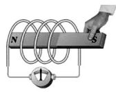
A solenoid is a device which can be used as an electromagnet.
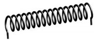
It is made of a long wire that has been wound many times into a tightly packed coil; it has the shape of a long cylinder.
Strength of an electromagnet
The strength of the electromagnet depends on the number of turns of the wire around the core and the amount of current passing through it.
The more the number of turns the more will be the magnetic effect.
The iron nail attracts two safety pins when wrapped with a coil with more number of turns.
What will happen if the current passing through the coil is switched off?
The iron piece will lose its magnetic effect, i.e., it will stop behaving like a magnet and, thus, will not attract the safety pin.
Uses of Electromagnets
Electromagnets are used in cranes to pick up cars in scrap yards and also to separate iron from garbage dump.
They are also used in loudspeakers, telephones, electric motors which are used in electric fans, washing machines, refrigerators, etc.
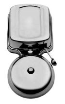
Electromagnets are also used in Electric Bell.
What do you do when you reach your friend’s house to let him/her know that you are at the door?
You ring the doorbell.
Do you know what makes the bell ring?
An electric bell has an electromagnet that pulls a strip of iron which makes the hammer hit the gong to ring the bell.
Let’s study how an electric bell works . . .
Electric Bell: What do you do when you reach your friend’s house to let him/her know that you are at the door? You ring the doorbell.
Do you know what makes the bell ring? An electric bell has an electromagnet that pulls a strip of iron which makes the hammer hit the gong to ring the bell.
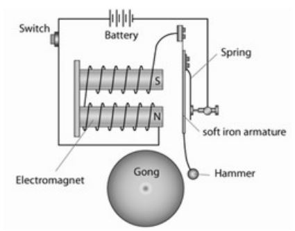
Step 1: When you push the switch of the bell, an electric current flows to the electromagnet.
Step 2: The electromagnet attracts the soft iron strip. The hammer attached to the strip then hits the gong, causing a ring.
Step 3: When the soft iron strip gets attracted to the electromagnet, it no longer touches the screw (interrupter) and hence the circuit is broken (much like a switch being turned off).
This turns off the electromagnet and it can no longer attract the soft iron strip.
The soft iron strip returns to its initial position, touching the screw (interrupter).
This results in the circuit being complete, and current flows again.
Steps 1 to 3 repeat in quick succession as long as the switch is on. This is how we hear a
continuous ring of the bell.
Electric Buzzer: Nowadays, we use electric buzzers and music bells, which work on a principle different from that of the electric bell described here. Buzzers are of different types.
Chemical Effect: This effect is used in electroplating, electrotyping, purifying metals, electrolysis etc.
Here electrical energy can be used to produce chemical reaction in solutions.
7. ELECTRIC CIRCUIT
An electric cell or dry cell is the source of energy for the bulb to glow and warm up. Let us now learn the way in which this electric energy is made available to the bulb in the torch.
Making of a simple electric circuit
Step 1:
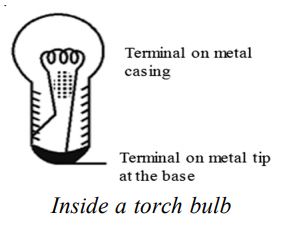
Take out the bulb from bulb from a torch. Examine the bulb carefully.
The bulb is a small globe of thin glass enclosing a coiled filament supported on two thick wires. One of these thick wires is connected to the metal casing around the base of the bulb. The other wire is connected to the metal tip at the base. The metal casing and the metal tip at the base are the two terminals of the bulb.
Step 2:
Take two pieces of insulated wire. Insulated wires have metal wire inside with a plastic covering on the outside. Remove the plastic covering from both the ends of each piece of wire. Fix these wires on the bulb as shown in the figure with the help of Insulating adhesive tape. Or fix the bulb on a bulb holder. The two screws on the bulb holder are the two terminals which are connected to the two terminals on the bulb. The two pieces of wire be connected to the two terminals on the holder, as shown in the picture.
Step 3:
Connect the two free ends of the wires from the bulb or the bulb holder to an electric cell in such a way that one piece of wire is connected to the positive terminals of the cell and the other to the negative terminal of the cell. This may be done with the help of a rubber band or an adhesive tape.
When you have finished with connections, the bulb lights up.
With your finger trace the path of the electricity from the positive ( + ve) terminal on the cell to the negative (–ve) terminal of the cell. It is a roundabout path travelled by electricity.
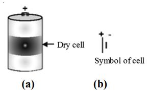
The dry cell has two terminals. The central terminal of the dry cell is called positive terminal. The base of the dry cell (which is made of a metal) is called negative terminal.
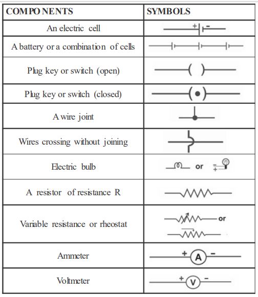
The above figure (a) shows the terminals of dry cell. The figure (b) shows the symbol for dry cell.
The long line represents positive terminal of the cell and the small and thick line represents negative terminal of the cell.
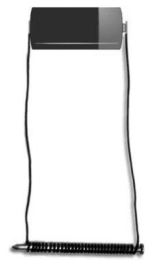
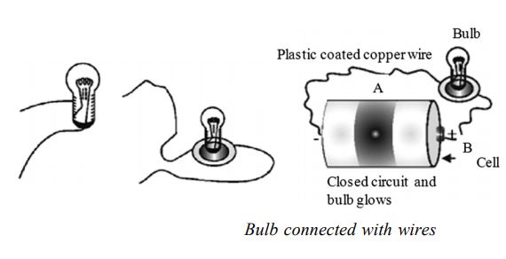
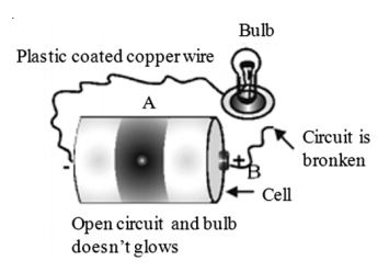
For this experiment you need a torch cell; a torch bulb marked 1.5 V, cellotape, a plastic coated 1 metre long copper wire and an old used blade.
Cut the plastic coated copper wire into two halves A and B. Remove plastic coating from each end of the wire such that 1 cm of plastic is removed. Now fix one bare end of each wire A and B to the terminals of 1.5 V bulb with the cellotape. Fix the other end of wire A to the base of cell with the help of cellotape. Now touch the bare end of wire B to the central terminal of cell as shown in figure. What do you observe?
The bulb lights up. This shows that electric current is flowing in wire A and B through the bulb.
The path along which electric current flows is called electric circuit.
Now remove the wire B from the central terminal as shown in figure. What do you observe? The bulb does not glow. It is because electric current does not flow, if the path is broken or path is incomplete.
Closed Circuit or Complete Circuit
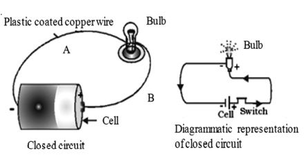
When the path which starts from one terminal of the cell, ends at the other terminal of the cell, without any break, then such a circuit is called complete circuit or closed circuit. When the circuit is closed, then any electric appliance in that circuit starts working. In the present case the bulb starts glowing.
Open Circuit or Incomplete Circuit
When the path of current, starting from one terminal of the cell to another terminal of the cell is broken or incomplete, then such a circuit is called open circuit or incomplete circuit.
For example, when we remove wire B from central terminal of cell, then the circuit is open circuit or incomplete circuit
Switches are used in the household wiring^ to open or close the electric circuit. When we switch on a particular electric appliance, we close the electric circuit.
Conversely, when we switch off an electric appliance, we open the electric circuit.
A switch, a simple device to ‘close’ or ‘open’ a circuit: An electric circuit passes through a
switch. Switch is a simple device which helps us to close or open the circuit. It helps in saving electricity
when not in use. You are always advised to switch ‘off the lights or other gadgets in your home to save electricity.
Ammeter is used to measure the current and voltmeter is used to measure the potential difference.
More details of ammeter and voltmeter shall be learnt in higher classes.
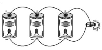
9. CONNECTING ELECTRIC CELLS IN SERIES
Take a dry cell and a torch bulb. Connect the bulb to the cell using copper wires as shown in figure. Observe the intensity- of light. The bulb does not glow brightly
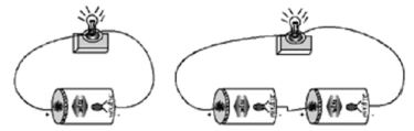
Now take one more dry-cell and connect two cells as shown in figure. In this method the positive of the first cell is connected to the negative of the second. The negative of the first and the positive of the second are connected to the bulb. The bulb now glows brighter.
In the battery torch or battery light two or three dry cells are put into a metal container in series.
The positive of one cell is connected to the negative pole of another cell in the series connection, When the, switch is turned on, the circuit is closed and the bulb glows and gives light.
Connecting Electric Cells in Parallel
Take three dry cells and connect them as shown in figure. That is all the positive poles of the three cells are connected together, and all the three negative poles are connected together.
These three positives and three negatives are connected to the bulb- You will observe that there is no change in the brightness of the bulb!
When cells are connected in parallel, their total electromotive force is the same as that if any one of them.
When cells are connected in series, their electromotive force is equal to the sum of the EMF of all the cells used.
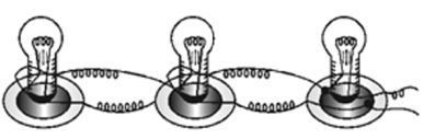
Connect three torch bulbs in series as shown in figure. Connect this to a dry cell and observe that brightness of each of the three bulbs. Now connect one more dry cell in series with he first cell. Observe the brightness of each of the bulb. Then connect one more dry cell in series with the first two cells. Again observe the bulbs.
Disconnect one of the three bulbs in the circuit. The circuit becomes open and all the three bulbs stop glowing. In series connection of bulbs,’ if one bulb gets fused, all the other bulbs in the series will stop working. Three bulbs connected in Series
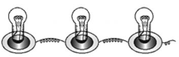
10. CONNECTING BULBS IN PARALLEL
Connect three bulbs in parallel. That is, one end of each of the three bulbs are connected one wire, the other ends of the three bulbs are con nected to another wire! These two wires are connected to a dry cell. All the three bulbs glow dimly. Now disconnect one of the bulbs. The other bulbs continue to glow as before.
To study the properties of (i) Series circuit, (ii) Parallel circuit
Materials required : a battery of four cells two bulbs of 1 watt each one fused bulb a switch few lengths of connecting wires cellotape.
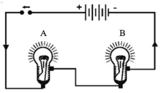
Method: Connect the bulbs A and B in series by connecting them to connecting wires with the help of cellotape as shown above. Connect the free ends of connecting wires to a battery through a switch.
Close the switch. What do you observe? Both the bulbs will glow. However, they will not glow very brightly. Open the switch. What do you observe?
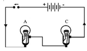
Both the bulbs will stop glowing.
Now remove the bulb B and instead fix a fused bulb C as in the above figure. What is your observation?
Bulb A does not glow.
Following are the conclusions from the above investigation
1. In series circuit all the appliances work simultaneously when switch is closed. Conversely, all appliances stop working when switch is open.
2. In series circuit, if any, of the appliances goes out of order, the other appliances stop working.
3. As the bulbs were not glowing very brightly, it can be concluded that in series the appliances do not work to their full capacity.
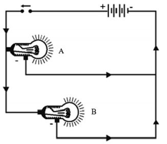
Now connect the bulbs A and B in parallel, such that they have common positive and common negative terminals as illustrated by Figure , through a switch and a battery.
Close the switch. What do you observe? Both the bulbs A and B glow very brightly. Now remove the bulb B and instead fix a fused bulb C Figure. What is your observation?
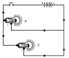
The bulb A continues glowing brightly, whereas bulb C does not glow. Following conclusions can be drawn from above investigation.
1. In parallel circuit all the appliances work independently
2. In parallel circuit if one appliance goes out of order, the other continues working. It means that each appliance in parallel circuit can be operated independently by a switch.
3. As the bulbs glow brightly, it means each appliance gets enough electric energy, and hence, works to its full capacity.
11. CONDUCTORS AND INSULATORS
The materials which allow the electric current to pass through them are the conductors of electricity and the materials through which electric current does not pass are the non-conductors or the bad conductors of electricity. Metals are the conductors of electricity. Non metals like glass, plastic, wood, paper, cloth and rubber are the non-conductors of electricity.
Non-conductors of electricity are also called insulators. All leads (wires) being used in an electric circuit are metallic wires coated with plastic or rubber. Coating of a conductor with a non-conductor is called insulation.
If we happen to touch a metallic end of a lead through which current is passing, it gives an electric
‘SHOCK’. The shock may be fatal too or otherwise it shakes the body and harms the person who has suffered the electric shock. Insulation saves a person from electric shock.