


3.1 ELECTRIC CURRENT
The rate of flow of charge in a circuit is called electric current. In other words, it is the amount of charge flowing per second. Denoted by letter I.
If Q is the charge which is flowing through a conductor in time t, then current is given by
Unit of Current
The S.I unit of current is ampere and it is denoted by the letter ‘A’.
The S.I unit of Q is coulomb and that of t is second.
Thus, the S.I unit of electric current is
Definition of Ampere
When a charge of coulomb flows through a conductor in one second, then the current flowing through the conductor is said to be one ampere.
Thus, when 1 coulomb of charge flows through a conductor in 1 second, then the current flowing through it is said
to be 1 ampere.
Smaller units of Electric Current
Sometimes smaller units of current are also used. These are microampere and milliampere.
1 microampere =
1 milliampere =
Bigger unit of electric current:
Sometimes the magnitude of the current flowing in a conductor is very large. This large magnitude of current is
expressed in bigger units, such as kilo ampere and mega ampere.
1 kilo ampere (kA) = 1000 A =
1 mega ampere (MA) = 1,000,000 A =
Flow of Current
In metals, the moving charges are the electrons constituting the current, while in electrolytes and ionized gases, electrons and positively charged ions are the ions moving charges which constitute current.
The charge on an electron is negative and is coulomb (symbol C). Therefore, IC charge is carried by electrons. Hence if I A current flows through a conductor, it implies that electrons pass in 1 second across the cross section of the conductor.
The direction of current is conventionally taken opposite to the direction of motion of electrons.
If n electrons pass through a cross section of a conductor in time t, then total charge passed
Q = n × e and current in conductor
Instrument by which current measured:
Current is measured by an instrument called ammeter.
3.2 CONDUCTION OF ELECTRICITY
1. Conductor: Substances which allow electricity to pass through them are called conductors; such as silver, gold, acidic solution, salt solution, etc.
2. Insulator: Substances which do not allow electric current to pass through them are called insulators; such as plastic, rubber, etc.
3. Good conductor and Bad Conductor: Substances which allow electric current to pass through them easily are called good conductors of electricity; such as silver, gold, aluminium, etc.
Some substances allows electric current to pass through them but in very little amount. Therefore, such substances called bad conductors of electricity, rather than being called as insulator.
In fact, most of the substances allow electric current to pass through them under certain conditions, so instead of using terms conductors and insulators, good conductors and bad conductors are used.
3.3 ELECTRIC CIRCUIT
An electric cell or dry cell is the source of energy for the bulb to glow and warm up. Let us now learn the way in which this electric energy is made available to the bulb in the torch.
Making of a Simple Electric Circuit
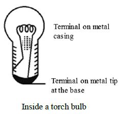
Step 1: Take out the bulb from bulb from a torch. Examine the bulb carefully.
The bulb is a small globe of thin glass enclosing a coiled filament supported on two thick wires. One of these thick wires is connected to the metal casing around the base of the bulb. The other wire is connected to the metal tip at the base. The metal casing and the metal tip at the base are the two terminals of the bulb.
Step 2: Take two pieces of insulated wire. Insulated wires have metal wire inside with a plastic covering on the outside. Remove the plastic covering from both the ends of each piece of wire. Fix these wires on the bulb as shown in the picture with the help of Insulating adhesive tape. Or fix the bulb on a bulb holder. The two screws on the bulb holder are the two terminals which are connected to the two terminals on the bulb. The two pieces of wire be connected to the two terminals on the holder, as shown in the picture.
Step 3: Connect the two free ends of the wires from the bulb or the bulb holder to an electric cell in such a way that one piece of wire is connected to the positive terminals of the cell and the other to the negative terminal of the cell. This may be done with the help of a rubber band or an adhesive tape.
When you have finished with connections, the bulb lights up.
With your finger trace the path of the electricity from the positive (+ ve) terminal on the cell to the negative (–ve) terminal of the cell. It is a roundabout path travelled by electricity.
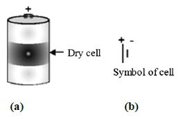
Step 4: The dry cell has two terminals. The central terminal of the dry cell is called positive terminal. The base of the dry cell (which is made of a metal) is called negative terminal. Figure shows the terminals of dry cell.
The long line represents positive terminal of the cell and the small and thick line represents negative terminal of the cell.
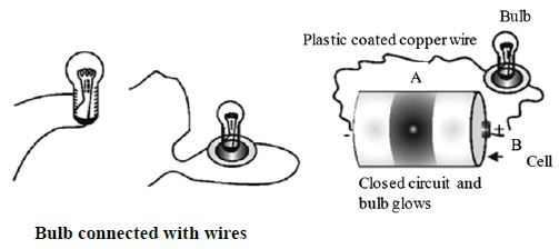
For this experiment you need a torch cell; a torch bulb marked 1.5 V, cellotape, a plastic coated 1 metre long copper wire and an old used blade.
Cut the plastic coated copper wire into two halves A and B. Remove plastic coating from each end of the wire such that 1 cm of plastic is removed. Now fix one bare end of each wire A and B to the terminals of 1.5 V bulb with the cellotape. Fix the other end of wire A to the base of cell with the help of cellotape. Now touch the bare end of wire B to the central terminal of cell as shown in figure. What do you observe?
The bulb lights up. This shows that electric current is flowing in wire A and B through the bulb.
The path along which electric current flows is called electric circuit.
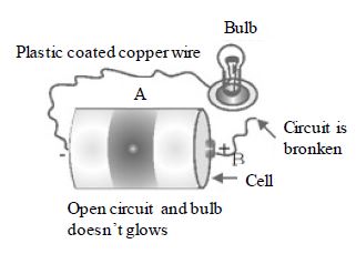
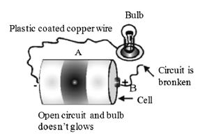
Now remove the wire B from the central terminal as shown in Fig. . What do you observe? The bulb does not glow. It is because electric current does not flow, if the path is broken or path is incomplete.
Closed Circuit or Complete Circuit
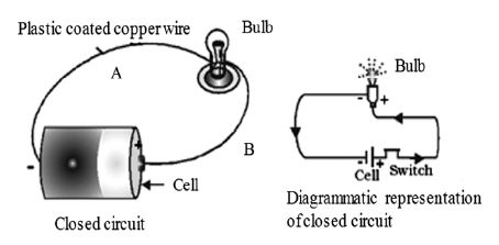
When the path which starts from one terminal of the cell, ends at the other terminal of the cell, without any break, then such a circuit is called complete circuit or closed circuit. When the circuit is closed, then any electric appliance in that circuit starts working. In the present case the bulb starts glowing.
Open Circuit or Incomplete Circuit
When the path of current, starting from one terminal of the cell to another terminal of the cell is broken or incomplete, then such a circuit is called open circuit or incomplete circuit.
For example, when we remove wire B from central terminal of cell, then the circuit is open circuit or incomplete circuit.
Switches are used in the household wiring^ to open or close the electric circuit. When we switch on a particular electric appliance, we close the electric circuit.
Conversely, when we switch off an electric appliance, we open the electric circuit.
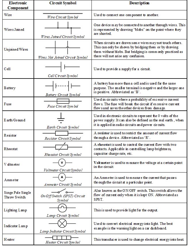
Symbols used in Electrical circuits:
You find hereunder some symbols used in electrical circuits.
A switch, a simple device to ‘close’ or ‘open’ a circuit: An electric circuit passes through a switch. Switch is a simple device which helps us to close or open the circuit. It helps in saving electricity when not in use. You are always advised to switch ‘off the lights or other gadgets in your home to save electricity.
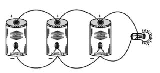
Connecting Electric Cells in Series
Take a dry cell and a torch bulb. Connect the bulb to the cell using copper wires as shown in Fig. . Observe the intensity- of light. The bulb does not glow brightly.
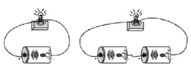
Now take one more dry-cell and connect two cells as shown in figure. In this method the positive of the first cell is connected to the negative of the second. The negative of the first and the positive of the second are connected to the bulb. The bulb now glows brighter.
In the battery torch or battery light two or three dry cells are put into a metal container in series. The positive of one cell is connected to the negative pole of another cell in the series connection, When the, switch is turned on, the circuit is closed and the bulb glows and gives light.
Connecting Electric Cells in Parallel
Connect one torch bulb to one cell as you did in fig. You, will observe that, the bulb toes not glow brightly.
Take three dry cells and connect them as shown in fig.. That is all the positive poles of the three cells are connected together, and all the three negative poles are connected together.
These three positives and three negatives are connected to the bulb- You will observe that there is no change in the brightness of the bulb!
When cells are connected in parallel, their total electromotive force is the same as that if any one of them.
When cells are connected in series, their electromotive force is equal to the sum of the EMF of all the cells used.
Connect three torch bulbs in series as shown in figure. Connect this to a dry cell and observe that brightness of each of the three bulbs. Now connect one more dry cell in series with he first cell. Observe the brightness of each of the bulb. Then connect one more dry cell in series with the first two cells. Again observe the bulbs.
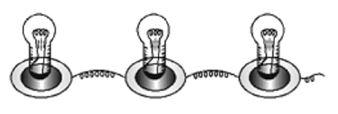
Disconnect one of the three bulbs in the circuit. The circuit becomes open and all the three bulbs stop glowing.
In series connection of bulbs,’ if one bulb gets fused, all the other bulbs in the series will stop working. Three bulbs connected in Series
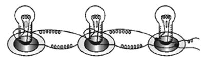
Connecting Bulbs in Parallel
Connect three bulbs in parallel. That is, one end of each of the three bulbs are connected one wire, the other ends of the three bulbs are con nected to another wire! These two wires are connected to a dry cell. All the three bulbs glow dimly. Now disconnect one of the bulbs. The other bulbscontinue to glow as before.
To study the properties of (i) Series circuit, (ii) Parallel circuit
Materials required : a battery of four cells two bulbs of 1 watt each one fused bulb a switch few lengths of connecting wires cellotape.
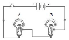
Method: Connect the bulbs A and B in series by connecting them to connecting wires with the help of cellotape as shown in Fig.(a). Connect the free ends of connecting wires to a battery through a switch. Close the switch. What do you observe? Both the bulbs will glow*. However, they will not glow very brightly. Open the switch. What do you observe?
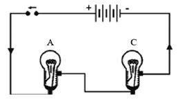
Both the bulbs will stop glowing.
Now remove the bulb B and instead fix a fused bulb C [Fig. ]. What is your observation? Bulb A does not glow.
Following are the conclusions from the above investigation.
1. In series circuit all the appliances work simultaneously when switch is closed. Conversely, all appliances stop working when switch is open.
2. In series circuit, if any, of the appliances goes out of order, the other appliances stop working.
3. As the bulbs were not glowing very brightly, it can be concluded that in series the appliances do not work to their full capacity.
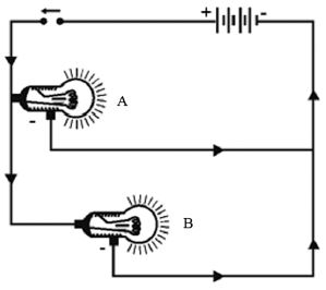
Now connect the bulbs A and B in parallel, such that they have common positive and common negative terminals as illustrated by Fig. , through a switch and a battery.
Close the switch. What do you observe? Both the bulbs A and B glow very brightly. Now remove the bulb B and instead fix a fused bulb C Fig. . What is your observation?
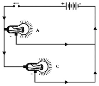
The bulb A continues glowing brightly, whereas bulb C does not glow. Following conclusions can be drawn from above investigation.
1. In parallel circuit all the appliances work independently
2. In parallel circuit if one appliance goes out of order, the other continues working. It means that each appliance in parallel circuit can be operated independently by a switch.
3. As the bulbs glow brightly, it means each appliance gets enough electric energy, and hence, works to its full capacity.
3.4 CHEMICAL EFFECTS OF ELECTRIC CURRENT
The passage of an electric current through a conducting solution causes chemical reactions. This is known as the chemical effect of electric current. Some of the chemical effects of electric current are the following:
• Formation of bubbles of a gas on the electrodes
• Deposition of metal on electrodes
• Change in colour of solutions
Example
(a) When electric current is passed through water, water dissociates into hydrogen and oxygen. Hydrogen is deposited over negative pole and oxygen is deposited over positive pole. Deposition of hydrogen and oxygen at different poles is visible in the form of bubbles.
(b) When electric current is passed through the solution of a metal salt, such as solution of copper sulphate, metal gets deposited at the negative pole, because metal is positively charged.
(c) Sometimes, the colour of solution also changes when electric current passes through it.
The above examples are some of the chemical effects of electric current. The chemical reaction depends upon the type of solution through which electric current is passed.
3.5 ELECTROLYSIS
• The process of decomposition of a chemical compound in a solution when an electric current passes through it is called electrolysis.
• The solution that conducts electricity due to the presence of ions is called an electrolyte.
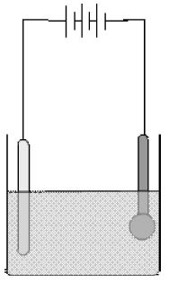
• Two electrodes are inserted in the solution and are connected to the terminals of a battery with a switch in between. This arrangement is called an electrolytic cell.
• The electrode that is connected to the positive terminal of the battery is called the anode, and the other connected to the negative terminal is called the cathode.
• The electrolyte contains ions, which are charged. The positively charged ions are called cations and the negatively charged ions are called anions. Cations, being positively charged, get attracted to the negatively charged cathode and move towards it.
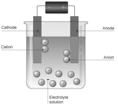
• On the other hand, anions, being negatively charged, get attracted towards the positively charged anode and move towards it. This is how ions move in an electrolyte and thus conduct electric current. A chemical reaction takes place at the electrodes.
• The reaction depends on the metals of which the electrodes are made and the electrolyte used. As a result of this reaction, we may observe bubbles at the electrodes due to production of gases, deposition of metal on the electrodes or change in the colour of the electrolyte.
• During electrolysis, the concentration of the electrolyte remains unchanged; the number of electrons extracted at the cathode is equal to the number of electrons supplied at the cathode; Since metal atoms are deposited on the cathode, the mass of the cathode increases and the mass of the anode decreases by an equal amount.
Elecrolysis is used in refining and extraction of metals from impure samples. This process is called electrorefining. It is also useful in coating one metal with another. This process is called electroplating.
• The reaction depends on the metals of which the electrodes are made and the electrolyte used. As a result of this reaction, we may observe bubbles at the electrodes due to production of gases, deposition of metal on the electrodes or change in the colour of the electrolyte.
• During electrolysis, the concentration of the electrolyte remains unchanged; the number of electrons extracted at the cathode is equal to the number of electrons supplied at the cathode; Since metal atoms are deposited on the cathode, the mass of the cathode increases and the mass of the anode decreases by an equal amount.
• Elecrolysis is used in refining and extraction of metals from impure samples. This process is called electrorefining. It is also useful in coating one metal with another. This process is called electroplating.
3.6 ELECTROPLATING
Electroplating is one of the chemical effects of electric current. Electroplating is a chemical process using which a metal is coated with a layer of another desired metal. Electroplating is done to make the metals shiny. Electroplating is done over the articles made of iron to make the iron shiny and to prevent iron from getting rusted.
Example
Wheel rims, handle of cycle, etc. are made shiny by the method of electroplating.
Process of electroplating
In the process of electroplating, metal salt solution is taken in a container. Salt of metal is chosen which is to be coated over another metal. Metal which is to be coated is dipped in the solution and connected with negative pole. Metal for desired coating is connected with positive pole.
When electric current is passed through the solution, metal from anode is dissolved in the salt solution and deposited over the negative pole (cathode). Thus, coating of desired metal is obtained on another metal.
Use of electroplating
(a) Water pipes, which are made of iron, are coated with a layer of zinc metal by the process of electroplating. Zinc is less reactive than iron and thus prevents the iron pipe from getting rusted.
(b) Rims of wheel of cycle, cars, etc. are electroplated with chromium metal. Layer of chromium metal give them shiny appearance and prevents from rust.
(c) Ornaments made of silver or other cheap metals are electroplated with gold to give them appearance like gold.
(d) Tin cans used for storing food are made of iron electroplating with a coat of tin. Tin is less reactive than iron, and prevent foods packed in them from getting spoiled.