


1. INTRODUCTION
Phenomena of light such as reflection, refraction, formation of images by mirrors and lenses are successfully explained by the assumption that light travels in straight lines. In all these phenomena light interacts with objects whose size is much larger than the wavelength of light (of the order of 10–7m), in which case we can ignore to a good approximation the wave nature of light.
The phenomena such as interference, diffraction, polarization etc., are studied under the title of physical optics, which can be explained by considering wave-nature of light i.e., The study of optical phenomenon is termed as wave optics or physical optics.
2. HUYGEN’S WAVE THEORY
It is based on a technique of conduction of wave front geometrically. The wave front is the locus of all medium particles vibrating in the same phase. i.e., in the same state of vibration.
Huygen’s principle:
1) Every point on a wave front vibrates in same phase with same frequency.
2) Every point on a wave front acts like a new independent source of light and sends at a spherical wave front, called a secondary wavelet.
3) Wave fronts move in space with the velocity of wave in that medium. Huygen’s wave could explain reflection, refraction, interference, and diffraction of light, but is failed to explain the phenomena of polarization of light.
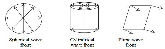
Wave front: The locus of all such particles of the medium which are vibrating in the same phase at any instant is called wave front (i.e. surface joining the points of same phase. The speed with which the wave front moves onwards from the source is called the phase velocity or wave velocity. The energy of the wave moves in a direction perpendicular to the wave front. There are three types of wavefronts.
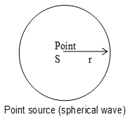
a) Spherical wave front: A spherical wave front is produced by a point source of light. This is because the locus at all such point which are equidistant from the point source will be a sphere. Spherical wave fronts are further divided into two headings. a)Converging spherical b) diverging spherical.
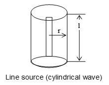
b) Cylindrical wave front: When the source of light linear in shape, such as a slit, the cylindrical front is produced. This is because all the points equal distance from a line source lie on the surface of a cylinder.
c) Plane wave front: A small part of a spherical or cylindrical wave front due to a distant source will appear plane and hence it is called a plane wave front. The wave front of parallel rays is a plane wave front.
Ray: The lines drawn normal to the wave front represent the path of light or rays of light.
Important:
1) Rays are perpendicular to wave fronts.
2) The time taken by light to travel from on a wave front to another is the same along any ring.
3. ELECTROMAGNETIC WAVE THEORY
James Maxwell was the proponent of the electromagnetic theory.
Maxwell assumed that a time varying magnetic field produces an electric field in space. Similarly, a time varying electric field produces magnetic field. These varying fields mutually interact. The net result of this interaction is what is termed as the electromagnetic wave propagating through space.
Properties of electromagnetic waves:
i) The electric and magnetic fields at any time are perpendicular to each other, and also to the direction of propagation.
ii) As the electric field vector and magnetic field vector oscillate in a direction perpendicular to the velocity vector v, the wave is a transverse wave.
iii) At every point in the wave at a given instant of time the electric and magnetic field strengths are equal.
iv) The velocity of propagation of electromagnetic waves depends on the electric and magnetic properties of the medium. According to Maxwell’s theory.
4. QUANTUM THEORY
The wave theory could explain phenomena such as interference and diffraction Phenomena arising from interaction of light with matter (photoelectric effect, Compton effect, etc.) could not be explained by wave theory. In these cases wave theory predicts results that are entirely different from experiment observation.
Trying to find an explanation of frequency distribution of radiation emitted by luminous bodies, Max Planck introduced the concept of radiation in definite indivisible packets of energy called quanta (quanta is plural form of quantum).
According to Planck, radiation of certain frequency emitted by a luminous body is made up of quanta of definite energy (E).
E = h
Here h is the Planck constant and its value is equal to 6.63 10–34 J.s.
The energy of a quantum is directly proportional to the frequency of the electromagnetic radiation. Since electromagnetic waves travel with the speed of light in vacuum, and as as c = where is the wavelength, from above equation we obtain.
i.e., the energy of a quantum is inversely proportional to the radiation’s wavelength in vacuum.
Einstein used Planck’s quantum concept in explaining photoelectric emission (photoelectric effect).
According to Einstein, light is a stream of quanta, called photons, (particle nature of light) traveling at velocity of light in vacuum. In beam of monochromatic light of frequency , all photons have the same energy given by h.
Einstein’s explanation of photoelectric effect in the light of quantum concept was a break-through in the field of physics. Arthur H. Compton provided yet another evidence of quantum (photon) nature of light by his experiment on scattering of X-rays.
5. COHERENT SOURCES
The sources of light which emit waves phase difference is zero of constant and does not vary with time are known as coherent sources.
Each atom or molecule acts individually and radiates light waves Combination of these waves is a wave train. The resulting wave trains differ in phase, and the phase varies rapidly and randomly. When the phase of wave trains changes randomly, the sources of those wave trains are said to be non-coherent sources. Non-coherent sources do not produce sustained interference patterns. Light detectors such as eye, photographic plate etc can not record such rapidly and randomly varying phase and the screen is therefore not chequered with bright and dark bands but is uniformly illuminated. Coherent sources can be realized if the two interfering wave fronts are derived from the same source as is done in the Young’s experiment.
Two sources are coherent if they have the same frequency and a constant phase difference. If two coherent sources emitting two waves of amplitude A1 and A2 superpose at point P. The phase difference between them at P is Q(which is constant). The resultant amplitude at P1 will be .
Similarly, the resultant intensity at P is given by
Here I1 and I2 are the intensity due to independent sources. If the sources are incoherent then resultant intensity at P is given by I = I1+I2
6. INTERFERENCE
If two or more waves of same frequency superimpose one upon another in a certain region of space the total energy is redistributed in such a way that at certain points intensity will be maximum and at others minimum. Interference of waves occurs according to principle of superposition.
This variation in intensity in the region of superposition of two or more waves whose phase relationship does not change with time is known as interference.
A path difference of L corresponding to phase difference .
7. YOUNG’S DOUBLE SLIT EXPERIMENT
The phenomenon of interference was first observed by Thomas Young in 1801 using sunlight. The experimental set up is schematically shown in fig.
A beam of sunlight is allowed to pass through a pinhole S in an opaque screen P. At some distance from P another opaque screen Q with two pinholes A and B is placed Pinholes A and B are very close and are symmetrically placed with respect to the pinhole S (i.e., A and B are equidistant from S). Another screen R is used to observe interference pattern at some distance away from Q. Young observed a few coloured bright and dark bands on screen R. Now a days we use a monochromatic light source and narrow slits instead of pinholes.
Explanation of Young’s experiment:
According to the Huygen’s principle when sunlight passes through pinhole S, spherical wave fronts are spread out. The two pinholes A and B are illuminated by these spherical wave fronts simultaneously.
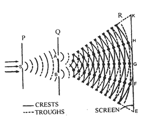
Then A and B act as two sources sending secondary spherical wavefronts. The radii of these wave fronts increase as they move from pinholes A and B and hence they superimpose on each other. In the circular arcs which are continuous represent wave crests and the dotted arcs represent wave troughs. In a wave train the troughs are out of phase by radians or 1800 with respect to the crests. Hence at points where a crest meets another crest or a trough meets another trough the resultant amplitude will be a maximum (constructive interference occurs), and at points where a crest due to one wave meets a trough due to another wave the resultant amplitude is a minimum (destructive interference occurs). The points of constructive interference are shown will asterisks, and points of destructive interference with small circles. The straight lines joining the points of constructive interference intersect the screen at points E, G, K (which appear bright) and the straight lines joining the points of destructive interference intersect the screen at points F, H (which appear dark). Thus on the screen, interference pattern with alternate bright and dark fringes is formed.
Theory: Let the separation between the slits A and B be ‘d’, and the screen R is at a distance D from the screen Q as in fig.
Now let us investigate the resultant intensity of light at a point P on the screen R as a result of interference. Let ‘a’ be the amplitude of each one of these waves from A and B and be the phase difference between them at the point P. Let the intensities of the individual waves be
Where K is the proportionality constant.
If y1 and y2 are the displacements of the waves, then
y1 = a sin t
y2 = a sin (t + )
Where is the angular frequency of the waves and is assumed to be constant with respect to time. The resultant amplitude at P is according to the principle of superposition.
Hence, y = y1 + y2 = a sin t + a sin (t + )
y = a sin t + a sin t . cos + a sin . Cost t
So y = a (1+cos ) sin t + a sin cos t
Now for solving this trigonometrical equation substitute
a(1 + cos ) = R cos
and a sin = R sin
in equation
Then y = R sin t cos + R sin + R sin . cos t
= R sin (t + )
This equation represents the resultant as simple harmonic motion with amplitude R and phase angle .
Now from equation
The intensity at the given point P can be written as I = KR2
Where K is the proportionality constant
Multiplying both the sides of by K we obtain
KR2 = 4Ka2 cos2 /2
This equation assumes the form
Where I0 = Ka2
The intensity of the resultant wave at any point P varies as changes.
i) When the phase difference = 0, 2, 4, …… m (2), the corresponding path difference L = 0, , 2 …….. m. For all these values of , cos2 /2 = 1 then the intensity I = 4I0. This is the maximum value of the intensity and a bright fringe occurs at that point P.
ii) When phase difference = , 3, 5 ….. (2m + 1) , the corresponding path difference , the intensity I = 0, we get a dark fringe at P.
The intensity varies between a maximum of I = 4I0 and a minimum of zero. This does not violate the principle of conservation of energy. Here the total energy is reallocated over the region of bright and dark fringes, the energy is neither annihilated nor created a new.
8. CONDITIONS FOR INTERFERENCE
1) The initial phase difference between the interfering waves must remain constant. Otherwise the interference will not be sustained.
2) The frequency and wavelengths of two waves should be equal. If the phase difference will not remain constant and so the interference will not be sustained.
3) The light must be monochromatic. This eliminates overlapping of patterns as each wavelength corresponds to one interference pattern.
4) The amplitudes of the waves must be equal. The improves contrast with Imax = 4I0 and Imin = 0.
5) The sources must be close to each other. Otherwise due to small fringe width the eye can not resolve fringes resulting in uniform illumination.
Important Points:
i) Angular width of a triangle
ii) If YDSE is done in a medium of refractive index () and wavelength of light is in the medium m then
a) Fringe width in the medium is given by
[where a = wavelength of light in air)
b) Position of bright fringe in the medium is given by
c) Position of dark fringe in the medium is given by
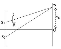
d) If A1 and A2 cross section area of the slit S1 and S2 and I2 and I2 intensity of source S1 and S2 then resultant power at P is given by
.
If point P is brightness point then cos = 1
If point P is darkness point then cos = -1
Illustration 1: Widths of two slits in Young’s experiment are in the ratio 4 : 1. What is the ratio of amplitudes and intensities of light waves from them.
Solution. Here,
If a, b are the amplitudes and I1, I2 are the intensities of light waves from them, then
Illustration 2 : Find the ratio of intensities at the two points X and Y on a screen in Young’s double slit experiment, where waves from the two sources S1 and S2 have path differences of zero and /4 respectively.
Solution. When path diff. is zero, phase diff. = 0.
∴ from
At Y, path diff. =
Phase diff. =
9. OPTICAL PATH
It is defined as distance traveled by light in vacuum in the same time in which it travel a given path length in a medium. If light travel a path length d in a medium of speed c, the time taken by it will be . So optical path length
Optical path = x d
It is also called optical path w.r.t. air where d = geometrical path in a medium.
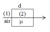
Note 1: In wave optics (wave motion) always optical path is consider. Optical path of medium (2) w.r.t. (1) is given by = (d=thickness of medium (2))
Path difference produced by a slab:
A slab of thickness t and refractive index 2 is kept in a medium of refractive index 1(<2). If two rays parallel to each other passes through such system, with one ray passing through the slab then the path difference product between them is due to slab will be
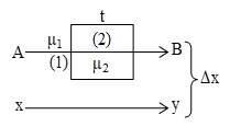
Case I: If 1=1 (ray travel in air, 2 = ) Path difference = ( – 1)t.
10. SHIFTING OF FRINGES
Suppose a glass slab of thickness t and refractive index is inserted onto the path of the ray emanating from source S1, the geometrical path difference between S2P and S1P is
x1 = S2P – S1P =
Path difference produced by glass slab x2 = ( – 1)t
Net path difference =
If point P goes to brightness then x = n
Earlier it was
Shift =
i.e. Whole fringe pattern shifts upward by a distance
Case (i): If point O goes the maximum then
Minimum thickness of glass for central point goes to maximum (n = -1),
Important Points: Following points are important with regard to equation (1)
a) Shift is independent of n, (the ordered fringe)
b) Shift is independent of , if white light used then shift of red colour fringe = shift of violet colour fringe.
c) Fringe width is same to earlier i.e.
d) Number of fringes shifted =
i.e. more number of fringes will shift of colour having smaller value of .
e) Minimum thickness of slab for central point of screen goes to brightness, t =
g) Minimum thickness of slab for central point of screen goes to darkness, t =
h) If glass slab inserted onto the path of the ray emanating from sources S1 then whole fringe pattern shifts upwards.
i) If glass slab inserted onto the path of the ray emanating from source S2. Then whole fringe pattern shifts downward. The position of nrh bright fringe given by
Fringe Visibility (V):
With the help of visibility, knowledge about coherence, fringe contrast an interference pattern is obtained.
If Imin = 0, V = 1 (maximum) i.e., fringe visibility will be best.
Also if Imax = 0.V = -1 and If Imax = Imin V = 0. (minimum) i.e., fringe visibility will be dull.
Interference in Thin Films:
1) Interference in reflected light : Condition of constructive interference (maximum intensity)
Condition of destructive interference (minimum intensity)
. For normal incidence 2 t = n
2) Interference in refracted light : Condition of constructive interference (maximum intensity)
. For normal incidence 2 μt = nλ
Condition of destructive interference (minimum intensity)
For normal incidence
Illustration 3: In a YDSE, λ = 6000 A0, D = 2m, d = 3mm, then a) Find the fringe width b) Find the position of the 3rd maxima. c) Find the position of the 2nd maxima.
Solution. a) Fringe width = 0.4 mm
b) Position of nth maximum is given by
c) Position of nth maximum is given by
Illustration 4: Light from a source consist at two wave length λ1 = 6500A0 and λ2 = 5200A0. If D=2m and d=6.5 mm find the minimum value of y where the maxima of both the wavelengths coincide.
Solution. We known position of bright fringe
Thus, fourth maxima of λ1 coincide with fifth maximum of λ2 = 0.8 mm
Illustration 5: In a YDSE, λ = 6000A0, D = 2m, d = 6 mm when a film of thickness t of refractive index 1.5 is introduced in front of the lower slit. The third maxima shifted to the origin.
a) Find the thickness of the film b) Find the positions of the fourth maxima.
Solution. Here film is introduced in front of the lower slit. So position of nth brightness is given by
a) by question, y3 = 0, i.e. n =3
b)
(above the origin)
(-ve indicate fringe below the origin)
Illustration 6: In a YDSE, λ = 60 nm, D = 2m, d = 6mm. Find the positions of a point lying between third maxima and third minima where the intensity is three-fourth of the maximum intensity of the screen.
Solution: We known
Here I1 = I2 = I0 (Let),
since point lies between 3 minimum and 3 maximum (n=3)
difference = (here n = 3)
Path difference = ⨯ phase difference
we known path difference in YDSE,
Illustration 7: Two coherent sources are 0.18 mm apart and the fringes are observed on a screen 80 cm away. It is found that with a certain sources of light, the fourth bright fringe is situated at a distance of 10.8 mm from the central fringe. Calculate the wave length of light.
Solution. Here, d = 0.18 mm
= 18 ⨯ 10–5 m,
D = 80cm = 0.8 m
n = 4 (for fourth bright fringe),
x = 10.8 mm = 10.8 ⨯ 10–3 m
For bright fringes,
m = 6.75Å.
Illustration 8: Green light of wave length 5100Å from a narrow slit is incident on a double slit. If the overall separation of 10 fringes on a screen 200cm away is 2cm, find the slit separation.
Solution. Here, λ = 5100Å = 5.1 ⨯ 10–7m
D = 200 cm = 2m, d = ?
As
Illustration 9: In Young’s experiment, two slits are 2.0 mm apart. The interference fringes for light of wavelength 6000Å are formed on a screen 80cm away.
a) How far is the second bright fringe from the central image?
b) How far is the second dark fringe from the central fringe?
Solution. Here, d = 0.2mm = 2 ⨯ 10–4m,
λ = 6000 Å = 6 ⨯ 10–7m,
D = 80cm = 0.8 m,
a) x = ? n = 2 (for second bright fringe)
b) x = ? n = 2 (for 2nd dark fringe)
11. APPLICATIONS OF INTERFERENCE PHENOMENON
Interference of light is used
i) to determine the wavelength of a monochromatic light and the difference between the wavelengths of two closely-spaced spectral lines.
ii) to determine the thickness of a thin transparent material
iii) to determine the refractive index of a liquid or a gas
iv) to test the flatness of surfaces
v) to test the reflectivity of the surfaces of lenses and prisms.
Exercise 1:
(i) Why cannot we obtain interference using two independent sources of light?
(ii) In Young’s double slit experiment, three lights, blue, yellow and red are used successively. For which colour, will the fringe width be maximum?
(iii) What is the ratio of slit widths when amplitudes of light waves from them have ration .
(iv) Bubbles of colourless soap solution appear coloured in sun light. Why?
(v) Two slits at a distance of 0.3mm are illuminated by light of wavelength 6000A0. Calculate the separation between second and third bright fringes on a screen 50cm away.
12. DIFFRACTION: PHENOMENON OF DIFFRACTION
It is our common experience that sound produced in an adjacent room is heard. This is made possible by the bending of sound waves at the edges of windows and other obstacles of moderate dimensions. This bending of sound waves is called diffraction of sound. Similarly, light waves also bend around the edges of obstacles, narrow openings, or aperatures and also penetrate in to the geometrical region of the shadow.
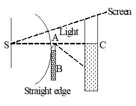
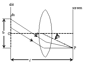
This phenomenon is known as diffraction. The amount of bending however depends upon the size of the obstacle and the wave length of the light. The bending is extremely small when the wavelength of light waves is small in comparison with the dimensions of the obstacle or openings. But when their dimensions are comparable with the wavelength of light, this bending becomes much pronounced. For example, when light waves diverging from a narrow slit S, which is illuminated by a monochromatic light source, go past and obstacle AB with a straight edge A, parallel to the slit, the geometrical shadow on the screen as shown in the fig is never sharp. A small portion of light bends around the edge (A) into the geometrical shadow (below the point C). Out side the shadow parallel to the edge, several bright and dark bands are observed. These bands are called diffraction pattern. The width of these bands goes on decreasing as one goes upwards and there is a bright uniform illumination far beyond point C.
The condition for observing the diffraction at an object (obstacle, narrow slits etc) on a screen is Where l is the distance between the screen and object, b is the size of the object and λ is the wavelength of light. There is a little difference between the formation of interference and diffraction patterns, though in both the cases, superposition of waves is involved. Interference is the result of superposition of light waves emitted by two or more number of separate coherent sources, where as diffraction is due to superposition of light wavelets originating from the subdivision of a wavefront into infinitely small coherent sources. These subdivided portions of the wave front act as continuous series of coherent sources.
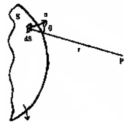
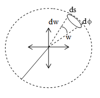
Diffraction can be explained by Huygens-Fresnel principle. According to this principle each point on a wavefront, which is unobstructed, acts as a source of secondary waves. The secondary sources are mutually coherent and the waves emitted by them interfere. It should be remembered that the diffraction effects are observed only when a portion of the wavefront is cut off by some obstacle. The amplitude at a point P due to the secondary wave depends on the angle between the normal to the primary wavefront and the line joining the wave front and the point P.
S is the primary wave front dS is an elemental area which acts as a secondary source, n is the normal to the primary wave front at dS, r is the distance between the secondary source (i.e., dS) and the point P, θ the obliquity, is the angle between the normal n and r as shown in the fig.
The effect of the whole wavefront of area S at point P is given by the sum of oscillations (displacements) due to individual elemental areas dS into which the wavefront is divided.
There are two approaches to explain diffraction. The first is Freshnel diffraction (general approach) and the second is Fraunhofer diffraction (a simplified approach)
a) Fresnel diffraction:
When the source of light, the obstacle and the screen are relatively close and are at finite distances, waves are spherical (or cylindrical); we are speaking about the Fresnel diffraction. No lenses are required to observe the diffraction pattern. In Fresnel diffraction , the wavefronts that approach the obstacle and proceed on to illuminate the screen at any point on it are plane ones, meaning thereby that the rays involved are not parallel. Therefore we call this investigation of diffraction a general one. Here, spherical or cylindrical wave fronts are divided in to large number of zones, the wavelets emanating from which superimpose to yield the variegated intensity distribution on the screen. The amplitudes and relative phases of all these zones are taken into account to calculate the intensity distribution. Hence mathematical treatment of Fresnel diffraction is often quite complicated. However we look into the salient features of this point of view.
Fresnel showed that the resultant amplitude at a point P due to a wavefront can be found by dividing a spherical or a cylindrical wavefront into zones. S is a point source. It sends a spherical wavefront in forward direction. Let the radius of the spherical wavefront be ‘a’ after certain time ‘t’. The effect of this wavefront at P is determined by dividing the wavefront into annular or ring –shaped zones. The distance from the edges of two successive zones to point P differs by . The annular zones having this property are known as Fresnel zones. The distance OP is b and equal to b0 of the zeroeth zone from point P i.e., b0 = b.
First zone is at a distance
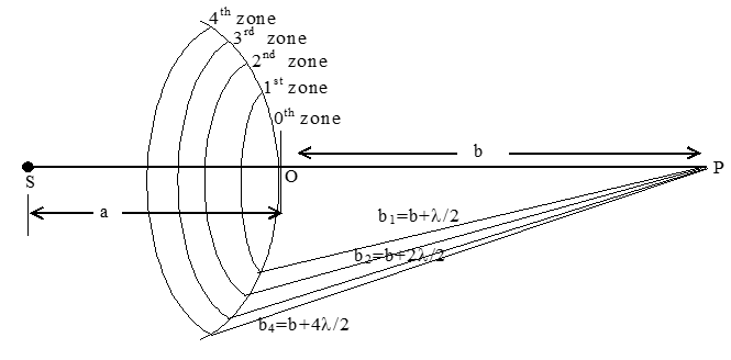
Second zone is at a distance
Third zone is at a distance
And the mth zone is at a distance
These zones are also known as half-period zones as a path difference of corresponds to a phase difference of 1800 which in turn corresponding to half a period. The areas of Fresnel zones are approximately the same when m is not too great.
The distance bm from the zone to point P slowly increases with zone number m. The obliquity θ also increases with m. The phases of the oscillations produced by adjacent zones differ by π or 1800 i.e., the amplitudes of the oscillations coming from the consecutive zones are alternately positive and negative. Therefore the amplitude A of the resultant oscillation at point P can be written as A = A1 – A2 + A3 – A4 + ….. Amplitudes of odd zones are with one sign and of even zones with opposite sign. The resultant intensity at P can be determined by the individual obliquity θ and the number of zones that superpose at that point.
b) Fraunhofer diffraction:
When the source of light and the screen are at infinite distances from the obstacle or aperture – we are speaking of Fraunhofer diffraction. The wavefronts involved in this type of diffraction are plane. To observe this diffraction, lenses are used. Fraunhofer diffraction is the limiting case of Resnel diffraction and is useful as its mathematical analysis is simple.
Let us briefly consider the Fraunhofer diffraction from a slit as shown in fig. A plane wavefront falls on a slit of width b. We place a converging lens between the slit and the screen. The screen is in the focal plane of the lens. The plane wave front, the slit and the screen are parallel to one another.
The wavefront area incident on the slit is divided in to elementary zones of width dx, parallel to the edges of the slit. The secondary waves emitted by the zones superpose at point P on the screen. The resultant intensity at P is determined by the angle θ called the angle of diffraction and the amplitude of the oscillation produced by different zones. The amplitude of the oscillation produced by a zone depends only on the area of the zone. The area of the zone is proportional to the width dx of the zone. Hence amplitude dA due to an oscillation produced by a zone of width dx at any point on the screen will have the form dA = C dx, C is a constant. The algebraic sum of the amplitudes of the oscillations due to all the zones at a point on the screen determines the intensity of the diffraction pattern.
The condition
determines the field of applicability regarding the Fresnel diffraction, Fraunhofer differaction and geometrical optics approximation.
If
Applications of diffraction:
i) The wavelengths of either monochromatic or composite radiations can be measured accurately by diffraction technique using diffraction grating.
ii) The wavelengths of X-rays are determined by X-ray diffraction.
iii) Structures of crystalline solids are determined by X-ray, electron and neutron diffraction measurements.
iv) Velocity of sound in liquids (organic or inorganic) can be estimated with the help of ultrasonic diffraction techniques.
v) Ultrasound scanning uses the principle of diffraction to assess the size and shape of ulcers, tumours etc in human body.22
13. FRAUNHOFER DIFFRACTION BY A SINGLE SLIT
Consider a parallel beam of monochromatic light incident normally upon a slit AB of width ‘d’. According to Huggen’s principle, each point of slit AB act as a source of secondary disturbance or wavelengths.
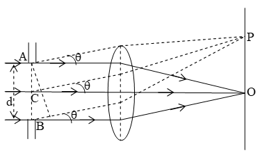
Now consider a point O on the screen which is placed at a distance D from slit AB. Since point O is equidistant from A and B. There, the secondary wavelets from AB reach the point O in the same phase.
Now let the light is diffracted through an angle θ so the secondary wavelets will be diffracted through an angle θ. Let these wavelets meet the screen at point P.
The point P will be of maximum or minimum intensity depending on the path difference between the secondary wavelets originating from the corresponding points of the wavelet. The path difference between wavelets starting from AB, BN = dsinθ.
a) For minimum: If the difference between the secondary wavelets originating from A and C (slit divided into two equal part) is equal to λ/2. So these wavelets will meet point P out of phase C.
(∴ Phase difference π) and hence destructive superposition will take place at P. Similarly the path difference between the wavelets originating from C and B is λ/2 and hence these will also produce destructive superposition at P.
Hence for first minimum (i.e. first dark fringe)
dsinθ1 = λ sinθ1 = λ/d
(θ1 is very small)
Thus for second minimum
dsinθ2 = 2λ sinθ2 = .
In general, from minima
dsinθn = nλ where n = 1, 2, 3, ………
b) For maxima: If path difference BN is odd multiple at λ/2 then constructive interference take place at P. Hence point P is point of secondary maxima.
Width of the central maximum:
Let f be the focal length of lens L (Placed very closed to the slit) and the distance of first minimum on either side of the central maximum be y.
Then
Since the lens L2 is very close to slit so f = D
(θ is very small tanθ x = sinθ)
This is the distance of first minimum on either side from centre of the central maximum.
∴ width of central maximum =
∴ Width of central maximum
The intensity distribution due to single slit diffraction is shown in figure
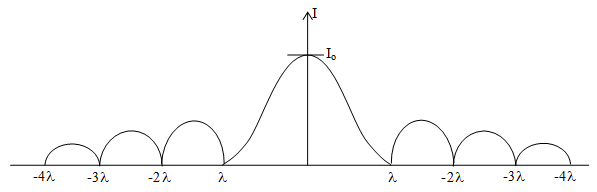
This shows that as we go away from central maximum, the intensity of secondary maxima decrease rapidly.
Illustration 10: The light of wavelength 600 nm is incident normally on a slit of width 3 mm. Calculate the linear width of central maximum on a screen kept 3m away from the slit.
Solution. Here, =
with of central maximum
=
Illustration 11: Two spectral lines of sodium D1 and D2 have wavelengths of approximately 5890Å and 5896Å. A sodium lamp sends incident plane wave on to a slit of width 2 micrometre. As screen is located 2m from the slit. Find the spacing between the first maxima of two sodium lines as measured on the screen.
Solution. Here, Å = 5890 ⨯ 10–10 m,
d = 2μm = 2 ⨯ 10–6 m Å
= 5896 ⨯ 10–10m,
D = 2m
For the first secondary maxima,
∴ Spacing between the first secondary maxima of two sodium lines
14. FRESNEL DISTANCE
Fresnel distance is defined as the distance of the screen from the slit when the spreading of light due to diffraction from the centre of the screen is equal to the width of the slit. It is represented as ZF.
We known the angular position of first minima on either side of the central maximum is given by
source θ1 =
The linear speed of the central maximum is given by
when D = ZF, y1 = d
Illustration 12: Light of wavelength 600 nm is incident on an aperture of size 2mm. Calculate the distance upto which the ray of light can travel, such that its spread is less than the size of the aperture.
Solution. Here,
15. DIFFRACTION GRATINGS
One of the most useful tools in the study of light and of objects that emit and absorbs light is diffraction grating.
1) this device consists parallel slits of equal width and equal spacing called rulings, perhaps as many several thousand per mm.
2) The separation (d) between rulings is called grating spacing (If N-rulings occupy a total width , then )
3) For light ray emerging from each slit at an angle θ, there is a path difference d sin θ, between each ray the one directly above. The d is called the grating element.
d = + e
where = width of the slit e = opaque part
4) The condition for formation of bright fringe is d sin θ = n λ, where n = 0, 1, 2 …. Is called the order of diffraction.
16. DIFFRACTION AND OPTICAL INSTRUMENTS (RESOLVING POWER)
The objective lens of optical instrument like telescope or microscope etc. act like circular apertures. Due to diffraction of light at a circular aperture a converging lens can not form a point image of an object rather it produce a brighter disc known as Airy Disc surrounded by alternate dark and bright concentric rings as shown in fig.
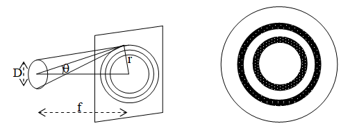
The angular half width of the Airy disc is given by
The lateral width of image (r) =
Where f is focal length of the lens, D is the aperture of the objective lens (diameter of lens). Each points on the object gives rise to a separate diffraction patter. If two points very close to each other, their central maxima superimpose on each other and the two images can be distinguished.
When the two images cannot be distinguished they are said to be unresolved. If the images are well distinguished, they are said to be well resolved. If the images are just distinguished, they are said to be just resolved.
Limit of resolution: The minimum distance of separation between two points so that they can be seen as separate (just resolved) by the optical instrument is known as its limit of resolution.
Resolving power: The ability of an optical instrument to form distinctly separate images of the two closely placed points or objects is called resolving power. Resolving power is reciprocal at the limit of resolution.
Resolving power
Important Points:
i) Resolving power of a telescope R.P = where D=diameter of objective lens of telescope.
ii) Resolving power of a microscope = where μsinθ is the numerical aperture of the objective lens.
iii) Limit of resolution of the telescope (dθ) = . It is also known angular resolution.
iv) Minimum distance of two objects which can be resolved by telescope.
Here for telescope.
x =
Comparison of interference and diffraction of light
| Interference | Diffraction |
| 1. In interference, bands are equally spaced | 1. In diffraction bands are unequally spaced. |
| 2. bands are large in number | 2. bands are a few in number |
| 3. Width of fringes are equal. | 3. The widths of fringes are not equal. |
| 4. The dark fringes are perfectly dark | 4. The dark fringes are not perfectly dark. |
| 5. All the maxima are of the same intensity. | 5. The bright fringes are of varying intensity. |
Exercise 2:
(i) In what way is diffraction from each slit related to the interference pattern in a double slit experiment?
(ii) How does the resolving power of telescope change when the aperture of the objective is increased?
(iii) A screen is placed 50 cm from a single slit which is illuminated with 6000 A0 light. If the distance between the first and third minima in the diffraction pattern is 3.00 mm, what is the width of the slit?
(iv) Determine the angular separation between the central maximum and first order maximum of the diffraction pattern due to a single slit of width 0.25 mm, when light of wavelength 5890 A0 is incident on it normally.
(v) Calculate limit of resolution of a microscope with cone angle of light falling on the objective equal tot 600. Take λ = 5000A0, and μ for air = 1.
17. POLARISATION
Unpolarised Light: According to Maxwell, light is an EMW. EMW consists of electric and magnetic field vectors which vibrate perpendicular to each other and both are also vibrate in all plane perpendicular to the direction of propagation of the light wave as shown fig.
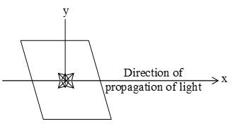
Light is represented by
E = E0 sin(t – kx) (electric field)
B = B0sin(t – kx) (magnetic field)
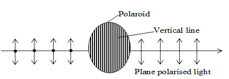
Pictorical representation of unpolarised light: Unpolarised light is represented as shown in fig.
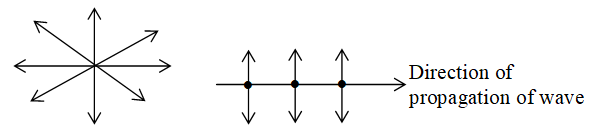
Represent compound of light vector in plane of paper.
Represent component of light vector perpendicular to plane of paper.
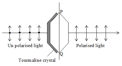
plane polarization of light: The phenomenon of restricting the vibrations of light wave in a particular direction in a plane perpendicular to the direction of propagation of light is called plane polarization of light.
Tournamaline crystal is used to polariser the light and hence is called polariser.
Note: When unpolarised light is incident on the polariser, the intensity of the transmitted polarised light is half the intensity of unpolarised light i.e. , where Io is the intensity of unpolarised light.
18. METHODS OF OBTAINING PLANE POLARIZATION
Plane or linear polarization can be achieved in number of ways i.e. by reflection, by refraction by scattering, by dichroism etc.
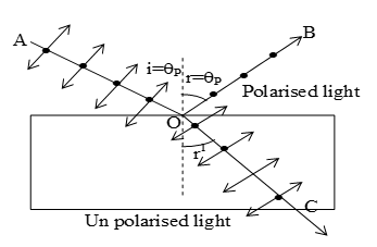
a) Plane polarization of light by reflection: Brewster discovered that when a beam of ordinary light is reflected from a transparent medium. The reflected light is completely plane polarized at a certain angle of incidence called the angle of polarization θp or Brewster angle.
According to this law, the refractive index of the transparent medium (μ) is numerically equal to the tangent of the angle of polarization (θP)
μ = tanθp
Experimentally, reflected component and refracted component of light are mutually perpendicular when ∠i = ∠θP.
Note: For an ordinary glass, the angle of polarization is about 570 and for water it is 530.
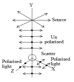
b) Plane polarisaton of light by scattering:
When light wave is fall on a transparent solid or small particles of dust, air molecule etc. It is absorbed by the electrons and re-radiated in all directions. The phenomenon is known as scattering.
Let a beam of un-polarised light be fall on a small dust particle along y-axis. Since light is transverse in nature, therefore, all the possible directions of vibrations in the unpolarised light are confined in x-z plane. Thus, the electron associated with the scatterer will be set into oscillations along X and Z axis and behaves as an oscillating dipole, emits light raditions in all directions except its own line of vibration.
19. POLAROIDS
Poaroid is a device used to produce the plane polarised light. It is based on the principle of selective absorption and is more effective than the tourmaline crystal. It is an extremely thin larger of crystalline substance called Herapathite.
Vertical lines of the Polaroid are the polarising direction of the Polaroid. The Polaroid transmits only those components whose electric field vectors vibrate parallel to the polarsing direction and stops the components of electric field vibrating perpendicular to the polarizing direction. The transmitted light is plane polarised light. The plane polarized light can be examined by the second polariser known as analyser. The plane of polarizer and plane of analyzer are perpendicular to each other.
Applications and uses of polaroids:
Polaroids have variety of uses in a daily life
1) In sun glasses
2) In trains and aeroplanes windows.
3) To record and reproduce three dimensional moving pictures.
4) In photo electric stress analysis.
5) In LCD i.e. liquid crystal display in calculators
6) In CD pagers
7) In solar compass
8) Polarisation is used as optical activity to study.
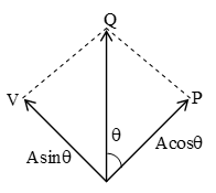
20. MALUS LAW
This law states that the intensity of the polarized light transmitted through the analyser varies as the square of the cosine of the angle between the plane of transmission of the analyser and the plane of the polariser.
Let A be the amplitude of the light transmitted by the polarizer and be the angle between the planes at the polarizer and the analser
Acosθ = component of A along P (i..e parallel to the plane of transmission of analyser)
Asinθ = component of A along OV (i.e. perpendicular to the plane of transmission of analyzer to the plane of transmission of analyzer)
We know Intensity (amplitude)2
I (Acosθ)2 I = kA2cos2θ = I0cos2θ
∴ I cos2θ Which is Malus law.
Special cases:
i) When θ = 0 (Planes of polarizer and analyzer are parallel to each other, then), I = I0
ii) θ = λ/2 i.e. planes of polarizer and analyzer are perpendicular to each other, I = 0.
Illustration 13: The refractive index of a medium is . The refraction, if the unpolarised light is incident on it at the polarizing angle of the medium.
Solution. Here,
As
As r = 900 – ip ∴ r = 900 – 600 = 300
Illustration 14: An unpolarised beam of light is incident on a group of four polarizing sheets, which are arranged in such a way that the characteristic direction of each polarizing sheet makes an angle of 300 with that of the preceding sheet. What fraction of incident unpolarised light is transmitted?
Solution. If I0 is intensity of unpolarised light then intensity of light from 1st polarising sheet =
Intensity of light from 2nd pol. sheet
Intensity of light from 3rd pol. sheet
Intensity of light from 4th pol. sheet
21. QUARTER WAVE PLATE AND HALF WAVE PLATE
A double refracting crystal cut parallel to the optic axis and of such a thickness that is introduces a path difference of or phase difference of between the ordinary and the extraordinary wave is called a quarter-wave plate. Exactly in the same way a crystal which introduces a path difference of λ/2 is called a half wave plate.
Let t = thickness of the quarter plate, μ0 = index of refraction for ordinary light
μc = index of refraction for extraordinary light then path difference = μ0t – μcθ
similarly (thickness of the half wave plate) t =
Exercise 3:
(i) What is the value of refractive index of a medium of polarizing angle 600?
(ii) Is head light of a car plane polarized?
(iii) Can you recognize by the unaided eye whether a given light is polarized or not?
(iv) Two nicols are so oriented that the maximum amount of light is transmitted. To what fraction of its maximum value is the intensity of the transmitted light reduced when the analyzer is rotated through
(a) 450 (b) 900 (c) 1800.
(v) At what angle should the axes of two polaroids be placed so as to reduce the intensity of incident unpolarised light to 1/3.
22. PHOTOMETRY
Photometry:
Photometry is that branch of Physics which deals with the practical measurement of intensity of light emitted by a source and also with the measurement of intensity illumination of a source.
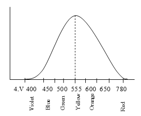
Standard luminosity curve:
Human eye responds to the visible part of light. Visible light consists of wavelengths ranging from 40000A to 7800A0. The sensitivity of human eye is different for different wavelengths of visible light. Sensitivity of human eye is defined as the sensation of sight produced for a given power per unit area if the light of the given wavelength falling on the eye. The variation of relative sensitivity of human eye with the wavelength of light is known as standard luminosity curve. Thus human eye is more sensitive to yellow and green colours than any other colours.
Luminous flux:
The visible radiant energy emitted per second by a light source is called luminous flux. It is denoted by . It is also known as photometric power.
SI unit of luminous flux is lumen (lm) and its dimensions are [ML2T-3].
Relative luminosity of a wavelength:
It is ratio of luminous flux of a source of a given wavelength to the luminous flux of a 555 nm source of same power.
Radiant flux:
The amount of visible and invisible energy emitted per second by a light source is called radiant flux. The unit of radiant flux is watt and its dimensional formula is [ML2T-3]. It is denoted by R
R =
Luminous efficiency ():
Luminous efficiency of a light source is defined as the ratio of luminous flux () emitted by the source to the radiant flux (R) of the source
i.e.
But R is considered equal to power (P) consumed by source
Luminous efficiency =
SI unit of luminous efficiency is lumen watt-1 (lm/W)
Solid angle:
(i) Solid angle is defined as normal area divided by the square of the distance i.e.
Solid angle () =
Where ΔA = r2, then solid angle, = 1.
The unit of solid angle is steradian. One steradian is the solid angle subtended by a part of the surface of a sphere at the centre of the sphere, when the area of the part is equal to the square of the radius of the sphere.
Note i) Total solid angle at a point = 4π
ii) If θ be the angle between positive direction of normal at spherical surface and distance r, then
Luminous intensity of source: (Illuminating power):
Luminous intensity (I) of a source of light in any direction is defined as the luminous flux emitted per unit solid angle by the source in that direction.
Mathematically,
= for an isotropic source, solid angle = 4π
Luminous intensity was initially known as illuminating power with unit candle.
Unit of luminous intensity is lumen/steradian (lm/sr) or candela (cd).
Intensity of Illumination (Illuminance) E:
Illuminance is defined as the luminous flux incidence normally on a unit area of a surface. It is denoted by E. It is also known as luminous flux density.
i.e. Illuminance (E) =
or
If is the luminous flux incident on the surface of area S then
In case of a point source
In case of a point source S = 2πrl
SI unit of illuminance is lux and cgs unit of illuminance is phot (cm candle)
One lux is the illuminance produced at the inner surface of a sphere of 1m radius when the source of 1 candela is placed at its centre.
1 lux =
One phot is the illuminance product at the inner surface of a sphere of 1 centimetre raidus when a source of 1 candela is placed at its centre
1 phot = 1 lm/cm2
Note:
i) 1 phot = 104 lux
ii) phot is bigger unit of illuminance than that of lux.
iii) Illuminance is directly related to the brightness of the illuminating surface.
Luminance of surface:
Luminance of a surface represents the luminous flux reflected by a unit area of the surface.
Luminance = illuminance x reflection coefficient
Luminance of surface is also defined as luminous flux per square metre coming from a surface in a given direction. It is denoted by B
B =
Illustration 15: How much flux passes through an area 0.5 m2 on a sphere of radius 25 cm, if a source of luminous intensity 800 candela is placed at its centre?
Solution. Here A = 0.5 m2, r = 25 cm = 25 x 10-2 m
I = 800 cd
E =
Flux () = E x A = 3200 x 0.5 = 1600 lumen.
Relationship between illuminance E and luminous intensity I for a point source:
Consider an element AB of surface area ΔS which subtends a solid angle d at the point source O. Let the normal to the surface at P makes an angle θ with the direction PO of the flux as shown in fig.
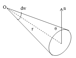
According to definition of luminous intensity
…………. (1)
We known
For a surface situated at a finite distance r is constant for a given source of light, I is constant.
The illuminance of the surface is directly proportional to the cosine of the angle between the direction of the central ray and normal to the surface. This is known as Lamberts cosine law.
Note: If the surface is perpendicular to the light beam, then θ = 0
In that case
E
23. INVERSE SQUARE LAW
Illuminance of a surface due to a point source of light is inversely proportional to the square of the distance of the surface from the point source. This is known as inverse square law.
Let a point source of light be placed at the centre of the sphere of radius ‘r’. The total luminous flux () emitted by the source falls normally on the inner surface of the sphere.
∴ Illuminance (E) =
as I is taken as constant.
∴ Er2 = constant E1r12 = E2r22
24. PRINCIPLE OF PHOTOMETRY
Principle of Photometry can be stated as the ratio of luminous intensities of two point sources is equal to the ratio of the square of their perpendicular distances from a screen where they produce same illuminance.
The illuminance at a distance r from the source of luminous intensity I is given by
Let I1 and I2 = luminous intensities of sources S1 and S2.
r1 and r2 = distance of sources from screen.
since
In case of a lens camera
i) Time exposure
ii) The ratio of focal length to the aperature of lens is called f-number of the camera
f number =
If f-number of camera is , it implies that aperture is of its focal length. f-number of the movie cameras is very low such as .
Exercise 4:
(i) A point source of 3000 lumen is located at the centre of a cube of side length 2m. Find the flux through one side of cube.
(ii) A hundred watt lamp has a luminous intensity 100 candela. Find the luminous efficiency of lamp.
(iii) The intensity of direct sunlight on a surface normal to the ray is I0. What is the intensity of direct sunlight on a surface whose normal makes an angle of 600 with the ray θ of the sun.
Answer to Exercise
Exercise – 1
(ii) red colour (iii) 2 : 1 (v) 0.1 cm
Exercise – 2
(iii) (0.2 mm) (iv) (0.53 ⨯ 10–3 rad) (v) (5 ⨯ 10–7 m)
Exercise – 3
(i) (iv) a. 50%,b. zero , c. 100% (v) 54.70
Exercise -4
(i) lumen. (ii) 12.56 lumen/watt (iii)
FORMULAE AND CONCEPTS AT A GLANCE
1) INTENSITIES OF MAXIMA AND MINIMA
a)
b) When sources are coherent, interference occurs
c) Intensity at any point, where phase difference is
d) When sources are incoherent, no interference occurs. Resultant intensity at any point
2) YOUNG’S DOUBLE SLIT EXPERIMENT
a. Position of bright fringes is given by , where n = 1, 2, 3 …. For first, 2nd, 3rd…… bright fringes.
b. Position of dark fringes is given by , where n = 1, 2, 3 …. For first, second third, ….. dark fringes.
c. Width of each bright/dark fringe
d. When the entire apparatus is immersed in a transparent medium of refractive index μ, fringe width, .
e. Angular width of interference fringes
3) FRESNEL DISTANCE
4) DIFFRACTION OF LIGHT AT A SINGLE SLIT
a) Condition for diffraction minima is , where n = 1, 2, 3 …… for 1st, 2nd, 3rd dark bands respectively.
b) Conditions for diffraction maxima is , where n = 1, 2, 3, …. For 1st, 2nd, 3rd, ….. bright bands respectively.
c) Width of central maximum,
d) Angular spread of diffracted beam (2θ) is calculated from
5) BREWSTER’S LAW AND LAW OF MALUS
a) , where iP is polarizing angel (Brewster’s law)
b) I = I0 cos2θ (Law of Malus)
SOLVED PROBLEMS-1
Prob 1. If the two slits in Young’s experiment have width ratio 1 : 4, deduce the ratio of intensity at maxima and minima in the interference pattern
Sol. As, intensity square of amplitude
or, or, b = 2a
Prob 2. In Young’s experiment, the width of the fringes obtained with light of wave length 6000 Å is 2 mm. What will be the fringe width if the entire apparatus is immersed in a liquid of refractive index 1.33?
Sol. As
Then,
or,
Prob 3. Find the ratio of intensity at the centre of a bright fringe to the intensity at the point one quarter of the distance between two fringes from the centre
Sol. Total intensity at any point is given by,
when, a = b
= 2 Ka2 (1 + cos )
At the central bright fringe, = 00
I1 = 2Ka2 (1 + 1) = 4 Ka2
Now, corresponds to a phase diff. =
Then, at
Hence,
Prob 4. Why is interference pattern not detected when the two coherent sources are far apart?
Sol. As, fringe width,
Therefore, when d is so large, the width may reduce beyond the visible region. Hence the pattern will not be seen.
Prob 5. Explain the statement “light added to light can produce darkness”.
Sol. When light waves from two coherent sources superimpose such that at any particular point, crest of one wave falls on trough of the other and trough falls on crest, the resultant wave is zero. Hence, resultant intensity is zero. This is the phenomenon of destructive interference. Thus light added to light can produce darkness.
Prob 6. A screen is placed 2m away from the single narrow slit. Calculate the slit width if the first minimum lies 5 mm on either side of the central maximum. Incident plane waves have a wavelength of 5000Å.
Sol. Here, D = 2m, x= 5 mm = 5 ⨯ 10–3m
λ = 5000Å = 5000 ⨯ 10–10m = 5 ⨯ 10–7m
For the find secondary minima,
or,
Prob 7. Two nicols are so oriented that the maximum amount of light is transmitted. To what fraction of its maximum value in the intensity of transmitted light reduced when the analyzer is rotated through 600?
Sol. Net intensity transmitted is I = I0 cos2θ.
Here, θ = 300
Prob 8. Why can we not get diffraction pattern from a wide slit illuminated by monochromatic light?
Sol. When slit is wide (i.e., a > >λ), bending of light becomes so small that is cannot be detected upon a certain distance of screen from the slit. Hence practically no diffraction occurs.
Prob 9. Diffraction is common in sound but not common in light waves. Why?
Sol. For diffraction of a wave, an obstacle or aperture of the size of wavelength of the wave is needed. An wavelength of light is of order of 10–6m and obstacle/aperture of this size are rare, therefore diffraction is not common in light waves. On the contrary, wavelength of sound is of the order of 1m and obstacle/aperture of this size easily available, therefore diffraction is common in sound.
Prob 10. How are resolving power and limit of resolution of an optical instrument related?
Sol. Smaller is the limit of resolution, higher is the resolving power.
SOLVED PROBLEMS-2
Prob 1. In Young’s experiment, if the intensity ratio between bright and dark fringes is 25 : 9, ratio of intensities of interfering waves is
(A) 4 (B) 8 (C) 12 (D) 16
Sol. (D)
Then, Imax = for cos = 1
and Imin = for cos = – 1
Here,
or,
By components and dividends
or
Prob 2. The tip of a needle does not give a sharp image. It is due o
(A) Polarisation
(B) interference
(C) diffraction
(D) none of these
Sol. (C) When the size of an obstacle is of the order of wave length than light rays bend.
Prob 3. Light of wave length 6000Å is reflected nearly normal incidence from a soap film of refractive index 1.4. The least thickness of the film that will be black is
(A) (B) 1200Å (C) 2140Å (D) 1000Å
Sol. (C)
2 μt cosr= nλ, Here, r = 0
For n = 1,
Prob 4. Plane wave of λ = 600nm is incident normally on a slit of width 0.2mm. The total angular width of the central maximum is nearly
(A) 0.17′ (B) 0.170 (C) 0.17″ (D) 1.70
Sol. (B)
Prob 5. Two coherent monochromatic light beam of intensities I and 4I are superimposed. Maximum and minimum possible intensities in the resulting beam are respectively
Sol. Resulting intensity
Then, = 9I
And Imin =
Hence, correct choice is (C).
Prob 6. Plane microwaves are incident on a long slit having a width of 5cm. The wavelength of the microwaves if the first minima is formed at 300 is
(A) 25 cm (B) 5 cm (C) 2.5 cm (D) 5 mm
Sol. (C) d sin θ = nλ
For n = 1,
Prob 7. A wire of thickness 0.8 mm is placed between two glass plates making a wedge. The number of fringes visible is 1600. The wavelength of light is
(A) 10 μm (B) 100 nm (C) 1000 nm (D) none of these
Sol. (C) Here, 2t = nλ
or,
Prob 8. A parallel beam of light of wavelength 546m passes through a slit of width 0.4nm. The transmitted light is collected on a screen 40 cm away. The distance between two first order maxima is
(A) 0.55 mm (B) 1.1 mm (C) 1.65 mm (D) 2.2 mm
Sol. (B)
∴ separation = = 1.1 mm
Prob 9. Four nickel prisms one arranged 300 with respect to one another. A beam of intensity I0 from a lamp is incident on the first mirror. The intensity of beam emerging from 3rd nical prism is
(A) (B) (C) (D)
Sol. (C) Here, Ipol =I0/2
We know that, I = (Ipol Cos2θ) (cos2θ)
= (Here, θ = 300)
=
Prob 10. In YDSE the wavelength used is 600 nm. A transparent slice of thickness 36μ m is placed in the path of one wave. If the central fringe shifts to 30 th bright fringe from the centre then refractive index of the slice is
(A) 1.41 (B) 1.5 (C) 1.4 (D) 1.32
Sol. (B) (μ – 1) t = nλ
or,