


ELECTRIC CHARGES & FIELD
1. Introduction
The ‘Electrostatics’ a branch of Physics; deals with understanding the forces between stationary electric charges and also about the fields produced by those charges. Benjamin Franklin introduced the concept of two different kinds of charges. When a glass rod is rubbed with silk cloth, the charge accumulated on the glass rod is said to be positive and the charge accumulated on the plastic rod rubbed which fur is said to be negative. When an ebonite rod is rubbed with fur, ebonite rod acquires negative charge and fur positive charge. These examples strongly suggest that the electric charges are not generated but acquired by transfer from one body to another. Electrification is the process by which a body gets charged.
Substances are made of atoms. Atom consists of a positively charged nucleus around which the negatively charged electrons revolve in different orbits. The positive charge is contributed by protons in nucleus and negative charge is contributed by electrons. The amount of positive charge is equal to the amount of negative charge in an atom. Thus the net charge of the atom is zero and the atom is electrically neutral.
Now, if a body loses some of the electrons, there will be an excess of positive charge on it and the body becomes positively charged. On the other hand, if the body acquires an additional number of electrons, the body becomes negatively charged. When a glass rod is rubbed with a silk cloth, electrons from glass rod move on to the silk cloth. This transfer of electrons makes glass rod positive and silk cloth negative. When a plastic rod is rubbed with fur electrons from fur, are transferred to plastic rod and the rod becomes negative.
2. STUDY ABOUT ELECTRIC CHARGE
Conservation of electric charge
According to law of conservation of electric charges, the algebraic sum of positive and negative charges in an isolated system remain constant. Conservation of charge does not mean that charge cannot be produced or destroyed. It simply means that if ever charge is created or destroyed, it will always be in equal and opposite amount.
Following example illustrates the law of conservation of electric charge. It depicts the radioactive decay of uranium nucleus. Thorium nucleus and -particle are the products of the reaction.
Total charge before decay = + 92 e
Total charge after decay = +90e + 2e = 92 e
So total charge is conserved.
(Radioactive decay is the spontaneous disintegration of the nuclei of heavy elements)
Quantization of charge
The magnitude of the charge on an electron is denoted by ‘e’. Its value is . It is found in nature that any body can acquire an amount of charge (Q) equal to an integral multiple of the electron charge (e). No body is found to have a fractional value of e. Hence Q = ± ne, where n is an integer. Thus, charge is said to be quantized in units of e. The quantization of electric charge was experimentally proved by R.A. Millikan in his famous Oil drop Experiment.
Method of charging
Net static charge can be made to exist on an object by of the following methods.
(i) Charging by conduction
(ii) Charging by friction
(iii) Charging by induction
Friction electricity
The simplest way to experience electric charges is to rub certain bodies against each other. When a glass rod is rubbed with a silk cloth the glass rod acquires some positive charge and the silk cloth acquires negative charge by the same amount. The explanation of appearance of electric charge on rubbing is simple. All material bodies contain large number of electrons and equal number of protons in their normal state. When rubbed against each other, some electrons from one body pass onto the other body. The body that donates the electrons becomes positively charged while that which receives the electrons becomes negatively charged. For example when glass rod is rubbed with silk cloth, glass rod becomes positively charged because it donates the electrons while the silk cloth becomes negatively charged because it receives electrons. Electricity so obtained by rubbing two objects is also known as frictional electricity. The other places where the frictional electricity can be observed are when amber is rubbed with wool or a comb is passed through a dry hair Clouds also become charged by friction.
Some more Facts about charges and charged bodies:
Following are some more of the facts observed about electric charges and charged bodies.
1. Like charges repel each other and unlike charges attract each other. The force of attraction or repulsion between the charges exists even in vacuum.
2. The force between charges obeys inverse square law and its magnitude depends on the medium in which the charges are placed, the distance between them and also on the magnitude of the charges.
3. The electrostatic force is about 1035 times stronger than the gravitational force. So, the gravitational force between masses can be usually neglected in comparison with the electrostatic forces.
4. Bodies can be charged by friction, or conduction or by induction.
5. When a positive charge + q is brought nearer to an uncharged conductor, an equal and opposite charge -q will appear on the conductor on the side nearer. On the other side of the conductor a charge +q will appear in order to maintain the original uncharged (neutral) nature of the conductor. This process is called induction.
6. A charged body can attract an uncharged body due to induction of opposite charge on it. Thus induction proceeds attraction.
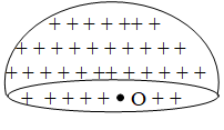
7. Any excess charge given to a conductor, always resides on the outer surface of the conductor.
8. Stationary charges are not affected by magnetic fields.
9. Charge does not undergo any change due to its motion.
10. The charge density ( , charge per unit surface area) tends to be very large on sharp points (having smaller radii of curvatures) on an isolated conductor. Lightning rods are used on tall buildings to prevent lightening from striking the building, works on this principle.
3. COULOMB’S INVERSE SQUARE LAW
Coulomb’s Law
French scientist Charles Augustine de Coulomb stated the inverse square law, known as Coulomb’s law.
“The force of a attraction or repulsion between two stationary electric charges is directly proportional to the product of the magnitude of the two charges and is inversely proportional to the square of the distance between them. The force acts along the straight line joining the two charges.”
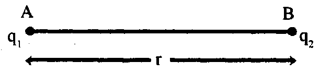
Consider two point charges q1 and q2 in rest at points A and B. The distance between the two charges is ‘r’ as shown in Fig. The force (F) acting between the two charges is proportional to q1q2 and inversely proportional to r2.
F q1q2
and
then,
. . . . . . (1)
The value of the proportionality constant K depends on the medium between the charges and also on the system of units in which the charges and r are expressed. In air or vacuum and in S.I. system K is equal to .
Here is called the permittivity of free space and its value is
Consequently
This is the mathematical form of Coulomb’s law.
In any medium other than the free space, the force is given by the Coulomb’s Law as
Here is the permittivity of the medium.
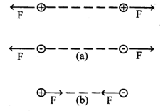
If the two charges are like charges (both positive or both negative) then q1 and q2 will have the same sign and F is positive and this represents the force of repulsion. If the two charges are unlike charges (one positive and another negative) then q1 and q2 will have opposite signs and F is negative. This represents the force of attraction. These details are shown in Fig. In all the cases the force is along the straight line joining the two charges.
(When there are more than two charges we use the principle of superposition to get the resultant force on a single charge.
Definition of coulomb
In S.I. system, the unit of charge is coulomb (C). If q1 = q2 = 1 C and r = 1m, we have from coulomb’s Law in free space, the force equal to 9 x 10⁹N.
Hence coulomb can be defined as follows, coulomb is that charge, which when placed at a distance of one metre in air or vacuum from an identical charge, repels it with a force of 9 x l09 N.
Permittivity of a medium
If we place the same two charges q1 and q2 at the same distance ‘r’ in different media, the force between the charges will be different. From Coulomb’s law in a medium we notice that the magnitude of the force changes with permittivity ( ) of the medium. The permittivity of the medium is its physical property which also plays a role in determining the magnitude of the force.
4. THE SUPERPOSITION PRINCIPLE
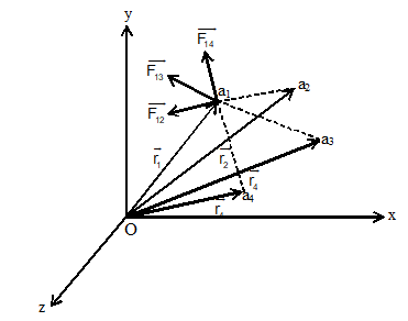
When number of charges are present, the total force on a given charge is equal to the vector sum of the forces due to remaining other charges on the given charge. Consider charge q1, q2, q3, ……………. qn located in vacuum at points whose position vectors w.r.t. origin O are respectively as shown in fig. Suppose we want to find the total force on charge q1 due to all other charges. Applying superposition principle, we have,
When
= Total force on charge q1.
force on q1 due to q2.
Force on q1 due to q3
= Force on q1 due to qn.
Note that is unit vector whose direction is from q2 to q1, is unit vector whose direction is from q3 to q1 and so on.
Note:
(i) The superposition principle holds good for electric forces and electric field.
(ii) We can use superposition principle to find (a) net force (b) net field (c) net flux (d) net potential (e) net potential energy due to a number of charges.
5. ELECTROSTATIC FORCE DUE TO CONTINUOUS DISTRIBUTION OF CHARGE
A system of closely spaced electric charges forms a continuous charge distribution. There are three kinds of continuous charge distribution. i) Linear charge distribution ii) Surface charge distribution (iii) Volume charge distribution.
1. Linear Charge distribution
(one dimensional): When charge is uniformly distributed over a line (straight or curve) we call it linear charge distribution. The charge per unit length is called linear charge density or line charge density. It is denoted by ().
dq = dl
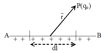
Consider a straight wire AB of length l on which charge q is distributed uniformly.
consider a small element length dl on the wire. Charge on the element of length dl is
dq = dl . . . . . . (i)
Electrostatic force on charge q0 placed at a point P at a distance r from the small element is
. . . . . . (ii)
Total force on charge qo due to the charge on the whole wire can be calculated by integrating equation (ii) over the length of the
2. Surface distribution of charge
When the charge is continuously distributed uniformly over a surface we call surface charge distribution. Charge per unit area is called surface charge density or area charge density. It is denoted by (s). Unit of s is C/m2.
dq = 6.dA
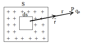
Consider a plane sheet of surface area S on which charge q is distributed uniformly.
Charge density of the surface, () =
Now consider a small element of area ds. Then charge on small element is dq = .ds
Electrostatic force on charge q0 placed at a point P at a distance r from the element is
Total force acting on q0 due to the charge on the whole surface is
3. Volume distribution of charge (three dimensions)
When the charge is continuously distributed over a volume, then we call it volume distribution of charge. Charge per unit volume is called volume charge density. It is denoted by (). Unit of is c/m3.
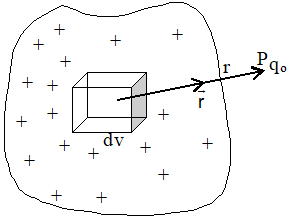
dq = .dv
Consider a surface of volume v having charge q.
Volume charge density () =
. . . . . . (i)
Now consider a small element of volume dv, then the charge on the element (dq) is
dq = .dv . . . . . . (ii)
The small force on q0 due to this element
. . . . . (iii)
Therefore, total force acting on the charge q0 due to the charge on the whole surface is
6. ELECTRIC FIELD
Usually the electric field is defined as the space around an electric charge where the electric force due to the charge is felt by another charge.
Intensity of Electric field or Electric field strength ():
The intensity of electric field or Electric field strength () at a point in space is defined as the force experienced by a unit positive charge placed at that point. We place a test charge , at the point and determine the force on it. Then field strength . Here, the test charge q0, should be infinitesimally small and positive.
The electric field strength is a vector quaintly. Its direction is the direction along which a positive charge placed at the point gets deflected.
The SI unit of electric field strength is Newton per coulomb (). Later we see that, it is also expressed in the units of volt per metre .
A uniform electric field is that in which at every point, the intensity of the electric field () is the same both in magnitude and direction.
A non-uniform electric field is that in which the intensity of electric field () changes from point to point either in magnitude or in direction or in both.
Electric lines of force
To visualize the electric field, Michael Faraday introduced the concept of lines of force.
A line of force is an imaginary line or curve along which a positive charge (free to move) would travel. The basic property of the electric line of force is that, the tangent to the curve at any point will be parallel to the direction of the electric field strength () at that point.
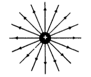
(a) Isolated positive charge
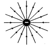
(b) Isolated negative charge
(c) Two positive charges
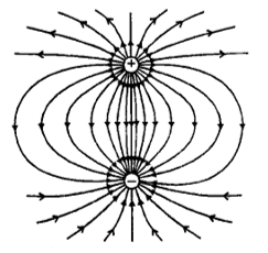
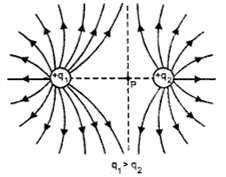
(d) Electric dipole
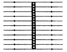
(e) Uniform field
The lines of force due to certain charges are shown in Fig. The lines of force in a uniform electric field are shown in Fig.
In uniform electric field the lines of force will be equidistant, parallel and straight lines.
Properties of electric lines of force
1. The tangent to the line of force at any point on it gives the direction of the electric field at that point.
2. The number of lines of force per unit area of cross section at any point is proportional to the magnitude of the electric field strength (E) at that point.
3. All lines of force diverge out from a positive charge. They converge in to a negative charge.
4. No two electric lines of force intersect each other. If they are to intersect at any point, at that point the electric field should have two different directions, which is not possible.
5. Electric lines of force will be normal to the surface of a conductor.
6. Electric lines of force are open lines. They start from positive charge and end on negative charge. On the other hand, magnetic lines of force are closed loops.
7. The lines of force are crowded where the field is strong and sparse where the field is weak.
8. The lines of force have no physical existence. They are just imaginary lines.
Force on a charge in an electric field
Since the force acting on a unit charge at any point is the electric field strength () the force experienced by a charge q at that point will be
If the charge q is positive, the force will be in the same direction as , if it is negative (for example an electron) the force will be in a direction opposite to .
Intensity of electric field (field strength) () due to a point charge
A point charge ‘q’ is placed stationary at O in air. We want to find out the electric field strength at a point P at a distance ‘r’ from the charge.
Place a positive test charge at P. From Coulomb’s Law, the force experienced by is given by (in magnitude).
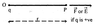
From this, the force experienced by a unit positive charge placed at P is given by
By definition this is the intensity of electric field (E) at P due to the charge ‘q’ at distance ‘r’ from it.
If ‘q’ is positive, E is along and if ‘q’ is negative will be along .
If the charge ‘q’ is in a medium of permittivity , and dielectric constant K.
The intensity of electric field in a medium (Emed) is given by
Evidently
Electric field intensity due to multiple charges
From the principle of superposition the electric intensity E at P due to the multiple charges is given by
The most important point to be taken care of here is that, all the individual intensities are to be added in a vectorial manner but not algebraically.
ELECTRIC POTENTIAL & GAUSS’ LAW
7. ELECTRIC POTENTIAL
The pressure difference determines the fluid flow and the temperature difference determines the of heat flow. Similarly, the potential difference between the two points is the physical quantity that determines the charge flow. A positive charge always flows from a point at a higher potential to a point at a lower potential. The electric potential is also used to describe the electric field strength.
The earth is a huge reservoir of charges and hence adding or removing some charges from it will not alter its potential. We consider the potential of the earth to be zero. Now, let us consider a positively charged body to be connected to the earth by a conducting wire as shown in Fig.
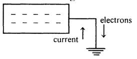
We know that a positively charged body has less number of electrons than usually required. Hence, electrons from the earth will flow through the conducting wire towards the body until the deficiency of electrons in the body is over come. The final state of the body will be electrically neutral. The potential of the body becomes zero, the same as that of the earth. The conventional current flows from the body to the earth until the body becomes neutral. In this case, we say that initially the body is at a positive (or higher) potential.
Let us now consider a negatively charged body to be connected to the earth by a conducting wire as shown in Fig. A negatively charged body has an excess of electrons. Hence, electrons will flow from the body to the earth through the conducting wire, until the body gets rid of the excess of electrons. Finally the body becomes neutral and will be at zero potential, same as that of the earth. In this case, conventional current flows from the earth to the body. The body is said to be initially at negative (or lower) potential.
Relatively speaking, higher potential is taken as positive and lower potential as negative. A neutral body will be at zero potential.
“The electric potential at a point in an electric field is defined as the work done in bringing a unit positive charge from infinity to that point against the electric field.”
Here, we consider that the electric field is produced by a charge and at an infinite distance from it, the field strength is zero.
If an amount of work W is done in bringing a test charge from infinity to a point against the electric field, then the potential at that point is given by
Work done in moving a charge q, through a potential difference V is
W = qV
In S.I. system, the unit of potential is joule/coulomb or volt (V) (Electric potential is a scalar quantity).
“The electric potential at a point is said to be one volt if, one joule of work is to be done in bringing one coulomb of positive charge from infinity to that point against the electric field.”
Potential difference
Potential difference between two points in an electric field is defined as the work done in moving a unit positive charge from one point to the other against the electric field.
The potential difference (P.D) is measured in volt. It is a scalar quantity.
Let potential at B be VB and at C be VC as shown in Fig.
The work done in bringing a unit positive charge from infinity to C against the field is VC, the potential at C. Similarly the work done in bringing a unit positive charge from infinity to B against is VB, the potential at B. Therefore, the work done in bringing a unit positive charge from C to B against the field is VB – VC (Evidently VB> VC). By definition the P.D. between B and C is
1. VBC will be positive if we go from B to C in the direction of the field.
2. In moving a positive charge from B to C we need not do any work. The field does work and the P.D. VC – VB will be negative.
3. The field produced by a positive charge is directed away from the charge. So, in bringing a positive charge from infinity to any point in this field, we have to do work and hence the potential at any point around a positive charge is positive.
Thus a positive charge gives rise to positive potential. A negative charge gives rise to negative potential.
4. The potential difference VB – VC between two points does not depend on the path we follow from C to B. The electrostatic field is a conservative force field.
Electric potential due to a point charge
Let us consider an isolated positive charge ‘q’ at O. The charge produces an electric field around it. We want to find out the electric potential at point P at a distance ‘r’ from the charge. The electric field along the direction . Let us consider a point A at a distance ‘x’ from O and lying on the same line OP as shown.
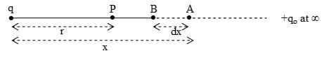
Electric field strength at A is given by,
along
Force acting on a test charge qo placed at A is
along .
Let the test charge be moved from A to B through an infinitesimal distance ‘dx’ against the field. Magnitude of the work done in this process is given by,
.
Total work done on the test charge qo in moving I from infinity to point P is given by
Potential at P by definition is given by
Hence,
Electric potential due to group of charges
Potential at a point due to group of N point charges is simply arrived at by the principle of super position.
8. POTENTIAL ENERGY OF A SYSTEM OF TWO CHARGES
Let us place particle charge q1 at A as shown. Let us now bring another positive charge q2 from infinity and place it at B which is at a distance r12 from q1. The potential at B due to q1 is
Hence, the work that is to be done in bringing charge q2 from infinity to B is given by
W =
This amount of work is called the electrostatic potential energy (U) of the system of two charges q1 and q2 U(q1, q2) = .
Electron volt
It is a unit of energy and is defined as the energy acquired by an electron that is accelerated through a potential difference of one volt.
Thus, 1 eV = 1.610–19 joule.
The energy levels and ionization energies of atoms and binding energies of molecules are usually expressed in eV units.
For example, the energy released for each fission of uranium nucleus is about 20 MeV=200 106 eV.
Relation between the electric field strength (E) and potential difference (V)
A and B are two points at a distance d in a uniform electric field . The potential difference between A and B is VAB = VA-VB = V. The work done in moving a charge q from to A against the field is
W = qV.
In the uniform electric field of strength , the magnitude of force acting on the charge q is
F = qE.
To move the charge a distance ‘d’ from B to A we have to apply an equal amount of force in opposite direction. Hence work done is,
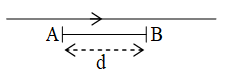
W = F.d = qEd.
or,
or, we can write
9. ELECTRIC FIELD AND POTENTIAL DUE TO VARIOUS CHARGE DISTRIBUTION
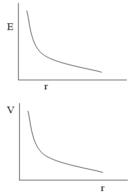
1. For point charge
and (here, )
Graph
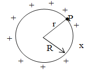
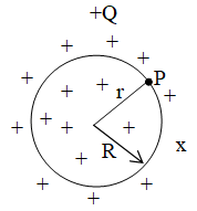
2. Charged circular ring
Suppose we have a charge circular ring of radius R and charge Q. On its axis electric field and potential is to be determined, at a point x distance away from the centre of the ring.
At point P,
and
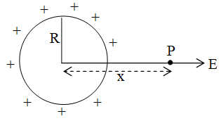
At centre, x = 0, so E = 0 and .
At the point on the axis such that x >> R, .
If .
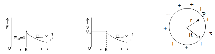
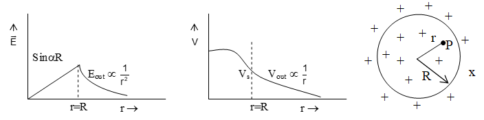
3. Charge conducting sphere (or shell of charge)
If charge on a conducting sphere of radius R is Q (and = surface charge density) as shown in figure. Then electric filed and potential in different situations
i) outside the sphere:
and

ii) At the surface of sphere: At surface r = R
and
iii) Inside the sphere:
Ein = 0 and Vin = Vs = constant.
Graph:
4. Uniformly charged non–conducting sphere
Suppose charge Q is uniformly distributed in to volume of a non-conducting sphere of radius R as shown below.
(i) Outside the sphere:
and,
Here, = volume charge density= .
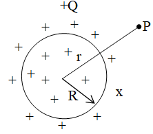
(ii) At the surface of sphere:
and
(iii) Inside the sphere: At the distance r from the centre:
and
at centre, r = 0, so Vcentre = and Ecentre = 0.
5. Infinite thin plate sheet of charge
Consider a thin infinite non-conducting plane sheet having uniform surface charge density in s. Electric field and potential near the sheet are as follows:
Potential due to concentric spheres
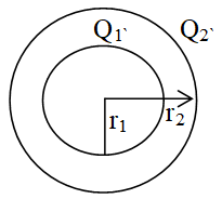
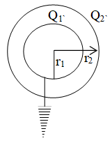
1. If two concentric conducting spheres of radii r1 and r2 (r2 > r1) carrying uniformly distributed charges Q1 and Q2 respectively.
Potential at the surface of each shell
2. Two concentric spheres having radii r1 and r2 respectively (r2 > r1). If charge on inner sphere is +Q and outer sphere is earthen then,
(i) Potential at the surface of outer sphere
or,
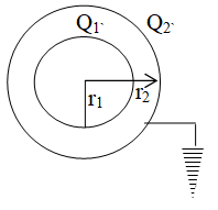
(ii) Potential of the inner sphere
3. If the outer sphere is given a charge +Q and inner sphere is earthed. Then
Equipotential surface
For a given charge distribution, locus of all points having same potential is called equipotential surface regarding equipotnetial surface following points should keep in mind.
(i) The density of the equipotential lines gives an idea about the magnitude of electric field. Higher the density larger the field strength.
(ii) The direction of electric field is perpendicular to the equipotential surfaces or lines.
(iii) The equipotential potential surfaces produced by a point charge or a spherically charge distribution are a family of concentric spheres.
(iv) Equipotnetial surfaces can never cross each other.
(v) The work done in moving a charge along a equipotential surface is always zero.
10. ELECTRIC DIPOLE AND DIPOLE MOMENT
Electric dipole
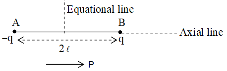
System of two equal and opposite charges separated by a small fixed distance is called a dipole.
Dipole moment
It is a vector quantity and is directed from negative charge to positive charge along the axis. It is denoted as and is defined as the product of the magnitude of either of the charge and the dipole length
i.e.
Its S.I. unit is coulomb-metre or debye.
1 debye = 2.310–30 cm (MoL1A1)
Important points
1. Electric field and potential due to an electric dipole. If a, e and g are three points on axis, equatorial and general position at a distance ‘r’ from the centre of dipole.
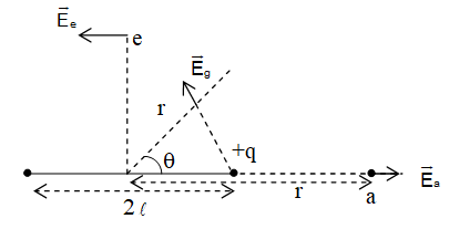
(i) At axis point
(directed from -q to +q)
(ii) At equipotential poin
(directed from +q to -q) and Ve = 0.
(iii) At general point:
and
2. Dipole is an external electric field: When a dipole is kept in an uniform electric field. The net force experienced by the dipole is zero.
(i) Torque: The net torque experienced by the dipole is
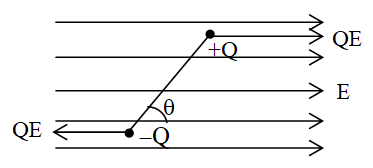
(ii) Work done: Suppose initially, dipole is kept in a uniform electric field at an angle . Now to turn it through an angle (with the field).
Wok done = PE (cos – cos)
If = 0 and = 0, W = PE (1-cos).
(iii) Potential energy: It is defined as work done in rotating a dipole from a direction perpendicular to the field to the given direction.
If q1 = 90o and
Then, W = U = -PE
(iv) Equilibrium of dipole: When = 0o i.e. dipole is placed along the electric field it is said to be in stable equilibrium.
When = 180o, i.e. dipole placed opposite to electric field, it is said to be in unstable equilibrium position it executes angular SHM.
where I = moment of inertia.
11. ELECTRIC FLUX & GAUSS’ LAW
Electric Flux
Electric flux is a measure of flow of electric field through a surface. It is equal to the product of an area element and the perpendicular component of integrated over a surface.
= Electric flux =
Its S.I. unit is volt-m or .
Gauss’s law
According to this law, the total flux linked with a closed surface called Gaussian surface is the charge enclosed by the closed surface i.e.
The electric field is resulting from all charge, both these inside and these outside the Gaussian surface.
Application of Gauss’s theorem
Gauss’s law is a very compact and elegant way to write relation between electric charge q and electric field . It offers a simple way to determine electric field when charge distribution is simple and symmetrical. In order to do so, we choose a proper Gaussian surface. Then Gauss’s law allows us to calculate electric field far more easily than coulomb’s law.
We shall illustrate the use of Gauss’s law to determine electric field for some important symmetrical charge distributions.
i) Electric field due to line charge:
Let = linear charge density of line charge AB
MNOP= cylindrical Gaussian surface (length l and radius r
E = Electric field at point C due to line charge
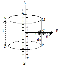
By use of gauss’s law, we can prove that the electric field intensity at point C due to line charge is equal to
. Where r is perpendicular distance from line charge.
ii) Electric field due to a uniformly charged cylinder:
let = Linear charge density of charge cylinder AB (radius a).
MNOP = cylindrical Gaussian surface passes through point C (length dl and radius r)
E = Electric field intensity at point C due to charge cylinder.
r = distance of point C from axes of cylinder (ra)
By use of Gauss’s law, we can prove that the electric field intensity at point C due to charge cylinder is equal to .
i.e.
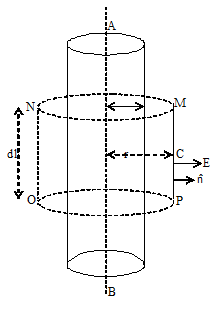
Note:
i) Electric field out the cylinder
ii) Electric field on the surface of cylinder
iii) Electric field inside the cylinder E = 0 (hollow cylinder)
iii) Electric field due to an infinity plane sheet of charge
By use of Gauss theorem, we can prove that the electric field intensity due to a plane sheet of charge having surface charge density is
For positive charge sheet, the field is directed towards outward normal.
Note:
i) For a charged mental plate, Ein side = 0 and Eout side = .
ii) The electric field due to a charge outside the Gaussian surface, contributes zero net flux through the surface. Because as many lines due to that charge enter the surface as leave it.
CAPACITANCE & CAPACITORS
12. CAPACITANCE
We know that, different containers having different volumes will have different capacities to hold a liquid. Similarly, different conductors will be having different capacities to hold electric charge. This capacity of the conductor to hold charge depends on the size, shape and surroundings of the conductor. The capacity of a conductor to hold charge is called its capacitance (capacity) and is analogous to the volume of a container.
Capacitance of a conductor
In the case of an isolated conductor, when we gradually increase the charge on the conductor, its potential also gets increased. At any instant, the charge ‘q’ on the conductor is directly proportional to the potential V of the conductor.
q V
that is q = CV
Hence C is the constant of proportionality and is called the capacitance of the conductor. Hence,
Capacitance C =
Definition of capacitance
The capacitance (capacity) of a conductor is defined as the ratio charge of (q) on it to its potential (V).
The capacitance of a conductor is numerically equal to the charge to be given to it to raise its potential by unity.
The SI unit of capacitance is farad (F).
The capacitance of a conductor is one farad (1F) if on adding one coulomb of charge (1C) to the conductor its potential raises by one volt (1V).
1 farad =
Farad is very large unit for practical purposes. Hence, its sub multiples are used as follows.
1 micro farad (1mF) = 10–6 F
1 pico farad (1pF) = 10–12 F
Working Principle of a capacitor
A capacitor is a device to store charges and electrostatic energy. In the simplest form, a capacitor consists of two parallel metal plates separated by a layer of air or a dielectric.
The capacitance of a conductor can be increased by increasing its size. Another way of increasing the capacitance is by lowering the potential of the conductor without altering the charge on it. This is the principle involved in a capacitor.
Let us consider a metal plate A and give it a positive charge q. Because of this charge, the potential of the plate raises to a value V. If C is the capacitance of the conductor, the charge on the conductor q = CV. At the potential V, the conductor A cannot hold more than charge q.
Now, as shown in figure bring an uncharged metal plate b nearer to the charged plate and keep parallel to it at a distance.
The positive charge q on conductor A induces an equal amount of negative charge on B. An equal amount of +q charge is induced on the outer side of B. The induced negative charge on B lowers the potential of A, where as the induced positive charge on B increases the potential of A. However, as the negative charge on B is nearer t the plate A, its effect will be more pronounced.’
Now, let us get the outerside of plate B be earthed as shown in figure.
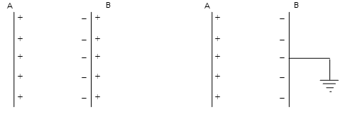
The induced positive charge on B gets neutralized due to earthing. While the induced negative charge on the inner side of B is held in position by the attraction of positive charge on A. As this negative charge on B lowers the potential of A, some more charge can be added to A (until its potential raises to V). There by the capacitance of plate A is increased.
The capacitance can be further increased by filling the space between the plates with a dielectric.
The principle of a capacitor is to increase the capacitance of a conductor by bringing nearer to it, an uncharged conductor and earthing the outer surface of the uncharged conductor.
Capacitors can be of any shape. Parallel plate capacitors spherical capacitors, cylindrical capacitors are in wide use.
Factors affecting capacitance
The capacitance of a capacitor depends on
1. The geometry of the plates
2. Separation between the plates and
3. The plates of the capacitor are charged with equal and opposite charges (+q and -q) by connecting them to the opposite terminals of a battery. The symbol to denote a capacitor is or. A capacitor whose capacitance can be varied gradually is represented by or
Uses of capacitors
Capacitors are very useful devices and are of special interest in physics and engineering applications.
1. Capacitors are used to establish desired uniform and strong electric fields in small space.
2. Capacitors can confine strong electric field for small volumes. They serve as useful devices for storing electric energy.
3. A capacitor blocks direct current and allows alternating currents. Capacitors are used in filter circuits.
4. Capacitors are used in generation and detection of oscillating electric fields.
5. Capacitors are widely used in tuning circuits of radio and T.V. receivers.
6. To reduce voltage fluctuations in electric power supplies, to transmit pulsed signals and to provide time delays capacitors are essential.
Dielectric constant of a medium
The dielectric constant (K) of a medium is defined as the ratio of permittivity of the medium to the permittivity of free space .
Dielectric constant has no units or dimensions.
K = or
The dielectric constant is also called the relative permittivity of the medium
The value of permittivity () and dielectric constant (K) depend on the temperature and pressure. The dielectric constant of the same material will have different values for direct current and alternating current. In case of alternating currents (A.C), the value of dielectric constant varies with frequency of A.C.
The value of dielectric constants at room temperature for certain materials are given in table.
|
Dielectric material |
Dielectric constant (K) |
|
Pyrex Glass |
5.6 |
|
Mica |
6.0 |
|
Nylon |
3.5 |
|
Rubber |
2.0 to 3.5 |
|
Sulphur |
4.0 |
|
Water (at 0oC) |
88.0 |
|
Water (at 20oC) |
80.0 |
|
Air (at 1 atm. Pressure) |
1.00059 |
|
Air (at 100 atm. Pressure) |
1.0548 |
|
CO2 (at 1 atm. Pressure) |
1.000985 |
Effect of dielectric on force between charges
The force between two charges q1 and q2 at a distance r, placed in air or vacuum is given by and in a medium it is
So, in a medium the force reduces by a factor K.
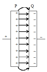
13. PARALLEL PLATE CAPACITOR
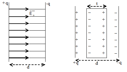
A parallel plate capacitor is the simplest type of capacitor. A parallel plate capacitor consists of two conducting metal plates P and Q each of area A as shown in figure. The two plates are kept at a distance ‘d’ and parallel to each other. The plates may be of any shape; (square, rectangular or circular). When we connect the plates to the opposite terminals of a battery, a charge +q appears on P and a charge -q on Q. On each plate the charge is uniformly distributed. If plate separation ‘d’ is very small compared with area of the plate A, the electric field between the two plates will be uniform as shown by the equidistant parallel lines of force. However, the field will not be uniform at the outer edges of the plates. This is shown by the curved lines of force in figure. This is called fringing and can be neglected when d << A.
When there is no material placed between the plates, air fills the space and acts as dielectric. With air as the dielectric the capacitance of the parallel plate capacitor in terms of plate area (A), distance between the plates (d) and the permittivity of air is given by
Another unit for permittivity
From equation we can write
as Co is in farad, A in metre2 and d in metre units, another unit of permittivity can be written as
14. DIELECTRIC MATERIALS
Any material that do not allow the electrical charges to easily pass through them is called insulator or dielectric material or simply a dielectric. All the materials are made of molecules. In certain kind of materials, ordinarily the molecules will have symmetric charge distributions. Such kind of molecules are called non-polar molecules. In the absence of any external electric field, a non-polar molecule will have its centre of positive charge coincide with centre of negative charge, as shown in figure.
But when placed in an external electric field , in each molecule the centre of positive charge will be displaced in the direction of the field, and the centre of negative charge in an opposite direction. This is shown in figure. Each molecule is said to get polarized. Let us see what happens when a dielectric made of non-polar molecules is placed in between the charged plates of a parallel plate capacitors. This is shown in figure.
In the electric field existing between the plates, each molecule of the dielectric gets polarized. Therefore, at the surface of the dielectric, charges appear. The entire dielectric gets polarized. These surface charges are of opposite sign to the actual charges on the plates and are called induced charges. Inside the volume of the dielectric, the nearby positive and negative charges cancel each other. Due to the induced surface charges at the surface of the dielectric, there will arise an induced electric field developed in a direction opposite to . Hence, the net electric field inside the dielectric is reduced to E = Eo-Ei. As a consequence, the potential difference Vo (without the dielectric) will get reduced to V(with the dielectric). It is actually found that
(i)
and (ii)
Here K = dielectric constant of dielectric. But, the charge on the plates remains the same as Q. The capacitance of the capacitor with dielectric will be
where Co is the capacitance without the dielectric.
Thus C = KCo with dielectric
Thus, the effect of introducing a dielectric between the plates of a capacitor is
(i) To increase the capacitance to K times the capacitance without the dielectric.
(ii) To reduce the electric field and potential to 1/K times the values without dielectric.
Dielectrics made of polar molecules
Certain dielectrics like water, hydrogen chloride and alcohol are made of molecules that have a non uniform distribution of electric charges. In such molecules, the positive charge centre will not coincide with the negative charge centre, even in the absence of any external field. This is shown in the figure. the molecules are polarized even in the absence of any external electric field. Such kind of molecules are called polar molecules. When such polar molecules are placed in an external electric field, the field will try to orient the positive charge centres in the direction of the field and the negative charge centres in the opposite direction. This is shown in figure when such a dielectric made of polar molecules is placed between the plates of charged capacitor, the effect will be similar to that of a non-polar dielectric and the effect will be more pronounced because, the molecules are already polarized even without the field. The capacitance will increase to C = KCo.
15. EFFECT OF DIELECTRIC ON THE CAPACITANCE OF A CAPACITOR
From the previous discussion of dielectrics, we know that the effect of completely filling the space between the plates of a capacitor with a dielectric is to increase the capacitance to C = KCo where K is the dielectric constant of the dielectric.
For a parallel plate capacitor,
Here is the permittivity of the dielectric.
If a dielectric slab of thickness ‘t’ and dielectric constant K is introduced between the plates of a capacitor as shown in figure, the capacity is given by
Capacitance of parallel plate capacitor with dielectric slab
Capacitance of a parallel plate capacitor having air (vacuum) between the plates of the capacitor is given by where A=area of each plate, d=distance between the plates. Now, let us introduce a dielectric slab of thickness t between the plates of the capacitor as shown in fig. Due to polarization, equal and opposite induced charges appear on the face of the dielectric slab. These induced charges produce induced electric field () (opposite to the direction of applied electric field ). The reduced value of the electric field in the dielectric ER = (E – Ep).
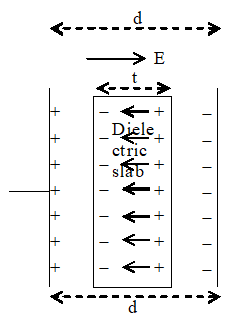
Potential difference between the two plates of the capacitor is given
V = ERt + E (d-t) [d-t thickness of air column]
Since
We know
Now, capacitance of the capacitor
. . . (i)
or
. . . . . (ii)
From equation (ii), it is clear that C > Co. Thus capacitance of parallel plate capacitor increases by the introduction of a dielectric slab between the plates of the capacitor.
If t = d i.e. then C = kCo.
Thus, capacity of parallel plate capacitor increases by a factor K (dielectric constant).
Capacitance of a parallel plate capacitor with conducting slab between the plates
Capacity of a parallel plate capacitor having vacuum between plates is given by
. . . . . . (i)
Where A = area of each plate, d= distance between the plates.
When a conducting slab of thickness t (t < d) is placed between the capacitor plates, the electric field extends over a distance (d-t) because field inside the conducting slab is zero.
Potential difference between the plates of the capacitor
We know, C =
or
Note:
i. If more than one dielectric slab is placed between the plates of capacitor then,
ii. If the slab completely fills the space between the plates then t = d and therefore
iii. If the space between the plates is completely filled with a conductor then t=d and k=¥
then C =
Important points
1. Capacity of a spherical conductor enclosed by an earthed concentric spherical shell: If a charge q is given to the inner spherical conductor it spreads over the outer surface of it and a charge – q appears on the inner surface of the shell. The electric field is produced only between the two produced only between the two. From the principle of generator the potential difference between the two will depend on the inner charge q only and is given by
Hence, the capacitance of this system
or
Hence, capacity per unit length =
From this expressions we see that if b = , C = 4p0a, which corresponds to that of an isolated sphere, i.e., the charged sphere may be regarded as a capacitor in which the outer surface has been removed to infinity.
2. Capacity of a cylindrical capacitor: When a metallic cylinder of radius a is placed coaxially inside an earthed hollow metallic cylinder of radius b (> a) we get cylindrical capacitor. If a charge q is given to the inner cylinder, induced charge – q will reach to the inner surface of the outer cylinder. Assume that the capacitor is of very large length (l >>b) so that the lines of force are radial. Using Gauss’s law we can prove that
Here, = charge per unit length
The potential difference between the cylinders in this case comes out to be:
16. COMBINATION OF CAPACITORS
Two or more capacitors can be joined together in different ways. The combination will have two end terminals. These are to be connected to the opposite terminals of a battery. If V is the potential difference applied to the combination and Q is the total charge drawn from the battery, then a single capacitor having its capacitance C = will have the same effect as the combination of the capacitors. This capacitance is called the equivalent capacitance or effective capacitance of the combination.
Series combination and parallel combination of capacitors are two types of combination of capacitors which are discussed below.
Series combination of capacitors
In series combination, the capacitors are first arranged in a series order that is the second plate of the first capacitor is connected to the first plate of the second capacitor, the second plate of the second capacitor connected to the first plate of the third capacitor and so on. Finally, the first plate of the first capacitor and the second plate of the last capacitor are connected to the opposite terminals of the battery.
In this combination, there is only one path for the charge to flow. So, the same charge appears on each capacitor. But the potential differences across different capacitors will be different.
Consider three capacitors of capacitances C1, C2 and C3 connected in series across a battery of potential difference V as shown in figure. The equivalent circuit with the equivalent capacitor C is also shown in the same figure separately.
Let the voltages accords the three capacitors be V1, V2 and V3 respectively.
The total P.D. across the series combination is
If C is the equivalent or effective capacitance of the series combination, and has same charge Q, then and
From above equations
For any number of capacitors in series, the effective capacitance can be written as
So, the equivalent capacitance in a series combination will be less than the least capacitance in the series.
In the case of two capacitors connected in series, the effective capacitance is
Parallel combination of capacitors
In the parallel combination, the capacitors are first arranged so that all the first plates of different capacitors are connected at one terminal and all the second plates of the capacitors are connected at another terminal. The two terminals are then connected to the two terminals of a battery. Thus, in the parallel combination, the P.D. across each and every capacitor will be same and equal to the P.D. across the battery. But the total charge drawn from the battery will be distributed differently on the different capacitors.
Consider three capacitors of capacitances C1, C2 and C3 connected in parallel across a battery of potential difference V as shown in figure along with the equivalent circuit capacitor as shown separately.
The P.D. across each capacitor is the same and is equal to the P.D. across the battery V.
The charge on first capacitor = Q1 = C1V.
Charge on second capacitor = Q2 = C2V
Charge on third capacitor = Q3 = C3V.
Total charge Q = Q1 + Q2 + Q3
= C1V + C2V + C3V
= (C1+C2+C3)V
If C the capacitance of the equivalent or effective capacitor, Q = CV
Hence, CV = (C1+C2+C3)V
C = C1+C2+C3
For any number of capacitors connected in parallel combination, the effective capacitance can be written as
C = C1+C2+C3+…….. + Cn
Evidently, the equivalent capacitance of parallel combination will be larger than the largest capacitance in the combination.
17. ENERGY STORED IN A CAPACITOR
Consider an unchanged capacitor of capacitance C. Its initial potential will be zero. Now charge the capacitor by connecting it across a battery. After the charging the final P.D. across the capacitor be V (same as the voltage across the battery terminals) and the final chare on the capacitor be Q.
At any intermediate state of the charging process, let the instantaneous charge on the capacitor be q and the P.D. across the capacitor be v. As the capacitance C of the capacitor is a constant and does not depend on q and v, we have q µ v. Hence, we can consider the final charge Q to be moved on to the plate through an average P.D. of can consider the final charge Q to be moved on to the plate through an average P.D. of
Hence the work done is equal to and this is the energy stored in the capacitor.
since Q = CV we have
with C in Farad, V in volt and Q in coulomb U will be in joules.
Effect of dielectric on the energy stored in a capacitor
We know that a dielectric placed between the plates of a capacitor increases its capacitance. It also effects the energy stored in the capacitors. This effect will be different (1) when the charging battery is disconnected from the circuit and (2) when the charging battery is present in the circuit and is continuing the supply of charges.
Let us consider a capacitor of capacitor of capacitance Co with air as the dielectric and charge it to a potential Vo with the help of a battery. Let the final charge on the capacitor plates be Qo.
Case 1. When the charging battery is disconnected from the circuit:
Let the battery be disconnected from the circuit, after charging and the space between the plates be filled with a dielectric of dielectric constant K.
Now, due to polarization of the dielectric, the potential will decrease and is
As the battery is not there to supply charges, the charge on the capacitor plates remains the same
Q = Qo
The capacitance with dielectric, will have a value
or C = KC
The energy stored, with dielectric will have a value
But is the energy stored before introducing the dielectric.
The energy stored gets reduced by a factor K when the battery is disconnected after charging the capacitor and then the dielectric is introduced.
Case (2): When the charging battery is not disconnected in the circuit:
Let the charging battery be present in the circuit and continue the supply of charges when the dielectric is introduced.
Initially, after introduction of the dielectric, the P.D. gets decreased to due to polarization of the dielectric. But, the battery is present and is supplying charges on to the plates. As a result, the charge on the plates increases until the P.D. attains the original value Vo. That is
V = Vo.
Charge on the plates increases to Q = KQo
Hence, the new capacitance
The energy stored in the capacitor with dielectric will be
.
Thus, the energy stored in the capacitor increases by a factor K when a dielectric is introduced between the plates with the battery present in the circuit.
Advantages of having dielectric in a capacitor
Many capacitors have a solid dielectric between their plates. This has the following advantages.
1. A solid dielectric keeps the two metal plates at extremely small distances of separation without actual contact.
2. A solid dielectric itself acts as a support to the upper plate.
3. The dielectric increases the capacitance by a factor K.
18. TYPES OF CAPACITORS AND THEIR USES
The simplest and basic form of a capacitor is the parallel plate capacitor. But, for different applications different types of capacitors are used. Some of the special types of capacitors are described below.
Variable capacitor
As the name itself indicates, the capacitance of a variable capacitor can be varied gradually. This is achieved by varying the effective area included between the plats. The plates are usually made of brass or aluminium and semi circular in shape. Variable capacitors are widely used in tuning circuits in radio and T.V. receivers.
A variable capacitor consists of two sets of plates. One set of plates is fixed in position and is called the stator. The other set of plates can be rotated over the stator by rotating the piston. The set is called rotor. During rotation of the rotor, the area common to the plates of stator and rotor is varied.
Multiple capacitors
This is a parallel combination of several parallel plate capacitors and is of fixed capacitance. Mica is used as the dielectric between a number of tin foils arranged in parallel.
If the capacitance between two successive plates (with mica as dielectric) is C, then the capacitance of the multiple capacitor is nC, where n is the number of dielectric plates used. The whole arrangement is sealed in a plastic case. These capacitors are used in high frequency oscillating, circuits. The dielectric constant of mica does not change much temperature and hence, these capacitors are used as standard capacitors in the laboratory.
Paper capacitor
In the paper capacitor a paper soaked in oil or wax is used as the dielectric. In between tin foils that serve as capacitor plates. To increase the capacitance to a large extent, several strips of metal foils and waxed paper are arranged alternately as shown.
Finally, the entire capacitor can be rolled and sealed in a cylinder. As these capacitors occupy small space and are cheaper in cost, they are widely used radio circuits and in laboratories.
Electrolyte capacitors
An electrolyte capacitor is obtained by passing a direct current between two sheets of aluminium foils with a suitable electrolyte like ammonium borate between the foils. Due to electrolysis, a very thin film of thickness of the order of 10–6 cm of aluminium oxide is formed on the anode plate and acts as the dielectric between the two plates. As the dielectric thickness is very small the capacitance will be very high. Care must be taken to connect this capacitor with proper polarity in a circuit. Otherwise the oxide film will break down. For this reason, in an electrolyte capacitor the polarity of terminals will be indicated.
These are widely used when high capacitances are required. Capacitances of the order of 103 mF can be easily obtained with electrolyte capacitors of small volumes.
SOLVED EXAMPLES
1. Which is bigger, a coulomb or charge on an electron? How many electronic charges form one coulomb of charge?
Sol. A coulomb of charge is bigger than the charge on an electron.
Magnitude of charge on one electron e = 1.6 10–19 coulomb.
Number of electronic charges in one coulomb,
2. The electrostatic force of repulsion between two positively charged ions carrying equal charge is 3.7 10-9N, when they are separated by a distance of 5 Å. How many electrons are missing from each ion?
Sol. Here, F = 3.7 10–9N
q1 = q2 = q, say
r = 5Å = 5 10–10m
n = ?
From Coulomb’s law,
As q = ne
3. Point charges having value +10C, +20C and -20C are placed in air at corners A, B and C of an equilateral triangle ABC having each sides equal to 10 cm. Find the resultant force on the charge at A.
Sol. Repulsive force on charge A due to charge B is
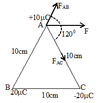
= 180N along BA.
Attractive force on charge at A due to charge C is
.
Here, FAB = FAC
angle between the forces is 1200
Resultant force (F) =
Since FAB = FAC hence, resultant force bisects the angle between the forces.
4. The force between two charges 2C and 4C is 24N, when they are separated by a certain distance in free space. Calculate the force if (a) distance between them is doubled and (b) distance is halved.
Sol. Here the charges remain the same, but only the distance is altered. Let the initial distance of separation between the two charges q1 and q2 be r. The force between them is
(a) When the distance is doubled,
(b) When the distance is halved,
5. Two pieces of copper, each weighing 0.01 kg, are placed at a distance of 0.1m from each other, one electron from per 1000 atom of one pieces transferred to other piece of copper. What will be the coulomb force between pieces after the transfer of electrons? The atomic weight of copper is 63.5 g/mole. Avogadro number = 6 1023.
Sol. Number of atoms in each piece of copper = .
No. of electrons transferred =
Charge transferred =
Force between charge =
6. An infinity number of charges, each equal to 4 mC are placed along x-axis at x=1m, 2m, 4m, 8m and so on. Find the total force on a charge of 1C placed at the origin.
So. Let F1, F2, F3 ………… Fn are of forces acting on the charge 1C due to charge q1, q2, q3 …………. qn.
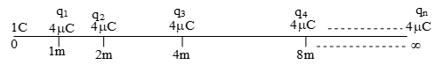
Total force acting on the charge 1C is
F = F1+F2+F3 + ……….. + Fn
(q1 = q2 = q3 = …………)
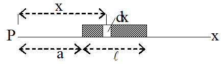
7. A thin rod has charge q distributed over its length l. The rod is placed as shown in the figure. Calculate the force on a test charge q placed at any point P on x-axis.
Sol. Linear charge density of rod
Let a small charge element of rod is dx at x distance from P
Charge on small element (dq) = .dx =
Force exert on test charge q0 by small charge dq is
8. When a charge of 1 C is placed in an electric field, it experiences a force of 2 10–3 N. Find the intensity of the field.
Sol. he charge, q = 1 10–6 C; Force experienced, F = 2 10–3 N
Let the intensity of the electric field be E.
Force experienced F = qE
.
9. Calculate force on an electron in a uniform electric field of 5 104 N/C due north.
Sol. Here,
E = 5 104 N/C, due north
F = – 1.6 10-19 5 104N
= – 8 10–15N
Negative sign indicates that force on electron will be due south, in a direction opposite to the direction of electric field.
10. Find the distance from a charge of 10C where the potential is 3104 V.
Sol. The charge, q = 10C = 10 10–6C.
Potential, V = 3 104 V.
Let the distance be r from the charge,
Then,
We have,
or,
11. Two protons at a distance of 0.5310–10 m. Calculate the potential energy of the system in eV.
Sol. Charge of the first proton, q1 = 1.6 10–19 C.
Charge of second proton, q2 = 1.6 10–19 C.
Distance between them r12 = 0.53 10–10 m.
Potential energy of the system
=
12. For charges q1 = – 0.02 C, q2 = 0.04C, q3 = 0.02 C and q4 =- 0.04 C are at the four corners of a square of side 9 cm. Calculate the potential at the centre of the square.
Sol. Each charge is at a distance r from the centre.
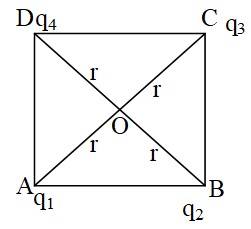
Then or,
.
Potential at the centre is given by,
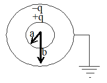
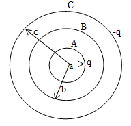
13. Figure shows two conducting thin concentric sheets of radii r and 3r. The outer shell carries charge q. Inner shell is neutral. Find the charge that flow from inner shell to earth.
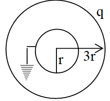
Sol. Let q’ be the charge on inner shell when it is earthed.
Vinner = 0
or
or
i.e. +q/3 charge will from inner shell to earth.
14. Three point charges are arranged at the three vertices of equilateral triangle as shown in fig. Calculate the electrostatic potential energy of the system if q = 3 10-7 C.
Sol. Given that q1=q, q2=2q, q3= -4q, r = 30 cm
= 0.3 m, q = 310-7C
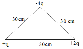
Electrostatic potential of the system of 3 charges is given by
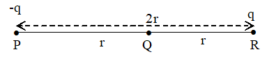
15. Three charges –q, Q and -q are placed at equal distances on a straight line. If total potential energy of system of three charges is zero, then what is the ratio Q : q?
Sol. Here, q1= -q, q2=Q, q3 = -q.
Total potential energy of 3 charges system given by
16. What is the magnitude of electric intensity due to a dipole of moment 2 10-8C – m at a point distant 1m from the centre of dipole, when line joining the point to the centre of dipole makes an angle of 600 with dipole axis?
Sol. Here,
17. An electric dipole consists of two charges of 0.1C separated by a distance of 2.0 cm. The dipole is placed in an external field of 105 N/C. What maximum torque does the field exert on the dipole?
Sol. Here, q= 0.1 C = 10–7C
Max value of
18. A charge Q is placed at a instance a/2 above the centre of a horizontal square surface of edge as shown. Find the flux of the electric field through the square surface.
Sol. Imagine a cube of edge a, enclosing the charge. The square surface is one of the six faces of this cube. According to gauss’s theorem,
Total electric flux through the cube =
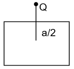
Electric flux through the square surface = .
19. When 1.0 1012 electrons are transferred from one conductor to another, a potential difference of 10V appears between the conductors. Calculate the capacitance of the two conductor system.
Sol. Here, charge transferred, q = ne
20. What is the area of the plates of a 2 fared parallel plate capacitor, given that the separation between the plates is 0.5 cm?
Sol.: Here, A = ?
C = 2 farad
D = 0.5 cm = 5 10–3m
0 = 8.85 10-12 C2N-1 m-2
As
21. An isolated sphere has a capacitance of 50 pF
a) Calculate its radius
b) How much charge should be placed on it to raise its potential to 104 V?
Sol. Given that C = 50 pF = 5010-12 F.
a) Capacitance of an isolated sphere is
22. A parallel plate capacitor has plates area 400 cm2 and separation between the plates is 2.0 mm. What potential difference will be developed if a charge of 2.00 C is given to the capacitor? If the plate separation is now increased to 4.00 mm, what will be the new potential difference?
Sol. Given that A = 400 cm2 = 40010-4 m2, d=2.00 mm = 210-3 m, q = 210-6 C
a) The capacitance of the parallel plate capacitor
Potential difference between the plates is
b) If the separation increase from 2.00 to 4.00 mm, the capacitance is decreases by a factor of 2. Potential increase by factor 2.
New potential = 25.65103 = 11.3103 V.
23. Three parallel metallic plates each of area A are kept as shown in fig. and charge q1, q2 and q3 are given to them. Find the resultant charge distribution. The six surfaces neglecting edge effect as usual.
Sol. Let charge on the face a, b, c, d, e and f are qa, qb, qc, qd, qe and qf respectively.
The plate separation does not affect the distribution of charge in this problem.
In the figure, qb=q1-qa, qd=q2-qc, qf = q3-qe.
Electric field at point P is zero i.e. Eq = 0.
At P3 charge qa will give an electric field towards right. All other charges qb, qc……… etc will give the electric field toward left. So,
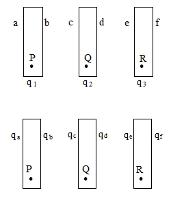
Similarly for R, ER = 0.
It will give result
Further we have a condition EQ = 0.
or
Note: i) Here we may conclude that, half of the sum of all charges appear on each of the two outermost surfaces of the system of plates.
ii) The pair of opposite surfaces like b, c and d, e carry equal and opposite charges.
24. Three concentric conducting shells A, B and C of radii a, b and c are as shown in fig. Find the capacitance of the assembly between A and C.
Sol. Consider a positive charge q on A and charge –q on C. Let potential difference between A and C is V.
25. It is required to construct a 10 mF capacitor which can be connected across a 200 V battery. Capacitors of capacitance 10 mF are available but they can withstand only 50V. Design a combination which can yield the desired result.
Sol. As each capacitor of 10 F can withstand only 50 V, therefore, to be connected across a 200 V battery, four capacitors must be connected in series in a row. Capacity of each row of four capacitors C1 is
For a total capacity of 10 F, four such rows of capacitors must be connected in parallel so that
Hence, we need 16 capacitors with 4 capacitors in series in each row and 4 such rows in parallel.
26. A metal sphere A of radius ‘a’ is charged to potential V. What will be its potential if it is enclosed by a spherical conducting shell B of radius b and the two are connected by a wire?
Sol. If q is charge on sphere A, then its potential is
When A is enclosed by a spherical conducting shell B, and the two are connected by a wire, the entire charge q of A shits to outer surface of B.
Potential of B will be
As sphere A is inside B, therefore, find potential of A =
27. A parallel plate capacitor has plate area 25.0 cm2 and a separation of 2.0 mm between the plates. The capacitor is connected to a battery of 12.0 V (a) Find the charge on the capacitor (b) The plate separation is decreased to 1.00 mm. Find the extra charge given by the battery to the positive plate.
Sol. Here, A = 25.0 cm2 = 25.0 10–4 m2
d = 2.0 mm = 2 10–3 m
V = 12 volt
a) Charge on the capacitor
b) When plate separation is decreased to half, capacity becomes twice. The charge becomes twice. Hence extra charge given by the battery
28. A parallel plate 100 F capacitor is charged to 500V. If the distance between its plates is halved, what will be the new potential difference between the plates and what will be the change in the stored energy.
Sol: Here, C = 100 F = 100 10–6F = 10–4 F,
V = 500 volt.
When distance between the plates is halved, capacity becomes twice i.e. C’=2C.
If V’ is new potential difference then as Q = C’V’ = CV
Energy stored,
29. Calculate the capacitance of a spherical capacitor consisting of two concentric spheres of radii 0.50m and 0.60m. The material filled in the space between the two spheres has a dielectric constant of 6.
Sol. Here C = ?
K = 6
30. A parallel plate air capacitor has a capacitance of 5F. On introducing a conducting slab of thickness equal to one fourth of the distance between the plates, what would be increase in capacity?
Sol.
When
Increase in capacity = C – C0
= 6.67 – 5 = 1.67F.