


1. INTRODUCTION
While Oersted’s surprising discovery of Electromagnetism had led to the more practical applications of electricity, it was the phenomenal discovery of Electro-magnetic induction in 1831 by Michal Faraday that among other things was the key to the practical generation of electricity, when he demonstrated experimentally that a voltage is generated across the length of a conductor if the magnetic flux normal to it is changing with time.
Interestingly, the outcome of his experiment could be interpreted as an instance of reverse symmetry applicable to the laws of Physics. Electric and magnetic fields up till the time had been believed to be produced by static charges and moving charges (or currents) respectively. Imposing an electric field on a conductor produces a current which in turn generates a magnetic field. The question here was, can a magnetic field generate an electric field? The answer to that came with Faraday’s experiment and it was proved conclusively that an electric field could be produced by a time-varying magnetic flux.
In the following sections we will make a detailed study and mathematical analysis of the concepts of magnetic flux, Faraday’s law of Electo-magnetic induction and it’s many fascinating applications.
2. MAGNETIC FLUX : B
Magnetic flux through a surface placed inside a Magnetic Filed is defined as
…………(1)
Where is an elemental area vector on the given surface and is the Magnetic Field vector at the given point.
IMPORTANT NOTE
1. If is uniform (i.e. the magnitude and the direction of the magnetic field is constant throughout space and also constant in time) and the surface in consideration is a plane ‘lamina’ (eg. a disc, rectangular surface etc), equation (1) can be simplified to
…………….(2)
Where is the magnetic field and is the area vector for the laminar surface and is a unit vector ‘normal’ to it.
2. If B is uniform in space but varies with the time then we use (2) but here represents magnetic field at any instant of time hence B is a function of time.
3. If B varies in space and with time then we use (1) but B becomes a function of time.
Physically, as in the case of the Electric Flux associated with a surface inside an electric field, Magnetic Flux for a surface, B represents the total number (algebraic sum) of lines of magnetic induction passing through a given area.
DIMENSIONS
, (Here F represents the force acting on a current carrying conductor of length L placed inside the magnetic field B )
UNIT
Since represents the SI unit for energy, the SI unit of magnetic flux is
[ as ampere = ]
= volt × sec [ as (joule/coulomb) = volt ]
and is called Weber = (Wb) or T×m2 (as Tesla = Wb/ m2 ).
The CGS unit of flux , Maxwell (Mx) is related to Weber (Wb) through the relation 1 Wb = 1V × s = 108 Mx
CALCULATING MAGNETIC FLUX
The magnetic flux associated with the given area in a field depends on the Magnetic field itself, , the area of the surface and also the angle between the area vector and the field, since for a given elemental area and magnetic field , flux is given by
This is illustrated with the following example : Consider an elemental area vector with the three different orientations w.r.t the magnetic field as shown,
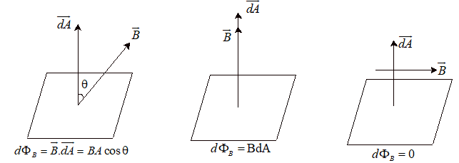
Thus magnetic flux is minimum i.e. for the case when (the last case), whereas magnetic flux is maximum when (second case).
3. MAGNETIC FLUX AS A VARIABLE QUANTITY
From the expression, it is evident that the Magnetic Flux will be a variable quantity (i.e a function of time) when either one or a combination of the parameters, , or the angle between them changes with time.
Change in flux due to change in Area
The Figure alongside shows a rod of length L moving with a uniform velocity v while in contact with two parallel rails. The parallel rails are also connected by a stationary rod at X=0 as shown such that the moving rod forms a ‘closed’ loop with the fixed rails and the other rod. The entire system is intersected by a uniform magnetic filed B normal to the plane of the loop. Calculate the Magnetic Flux associated with the closed loop as a function of time.
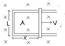
Sol. As shown in the fig. the direction of the magnetic field B and the area vector A both can be considered to be into the plane of the loop. The magnetic flux is now given by , where the value of the area , Therefore , as a function of time.
Change in flux due to change in angle θ
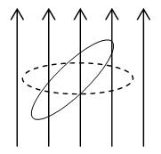
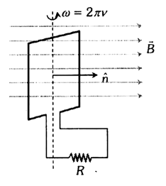
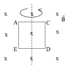
The figure alongside shows a closed rectangular loop (area A) rotating about a fixed axis (bisecting it) with a uniform angular velocity ω inside a uniform magnetic field as shown. Find the magnetic flux through the loop as a function of time (assuming the magnetic field lines to be tangential to the loop initially)
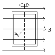
Sol. Let us assume that the loop rotates anti-clockwise as seen from top. We can denote the area vector , where rotates continuously such that it is initially (t=0) at with , whereas at time
Therefore the magnetic flux, as a function of time.
Note: (minimum value) and increases to maximum of as the rotation progresses.
Also, in this particular case the flux is both a ‘periodic’ and an ‘alternating’ quantity with respect to time. (Something important in the application of EMI to AC Generation later!)
4. ELECTRO MAGNETIC INDUCTION
In 1831, Michal Faraday independently demonstrated an important experiment whereby he was able to establish that if the magnetic flux associated with a closed conducting loop is made to continuously change, an electric current is ‘induced’ in the loop (even though it does not have a voltage source attached). This induced current will be observed as long as the magnetic flux is ‘changing’ but will cease if the flux becomes constant. This remarkable phenomenon is called Electro-Magnetic Induction (EMI).
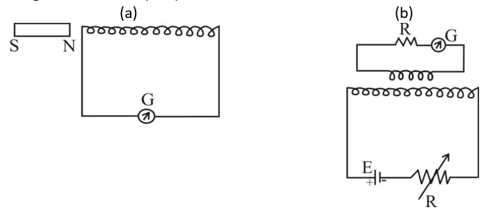
In the two possible schematic diagrams for such an experiment shown above, in (a) if the bar magnet is moved closer to the coil continuously a reading is observed in the galvanometer G. Also if the bar magnet is now moved continuously away from the coil, there again appears a reading, however the direction of the induced current observed reverses.
In setup (b), if the current through the coil in the circuit below is continuously varied using the variable resistance (Rheostat) shown, a reading is observed in the galvanometer G in the circuit above indicating an induced current. Again the direction of the induced current will change if the current in the lower circuit is made to increase as opposed to decrease.
5. Faraday’s experiment
The observations of Michael Faraday are illustrated in the following cases
i. Change in the field strength
When a bar magnet moves relative to a loop of wire, there is an induced current in the loop when the magnet and the loop are stationary, nothing happens
a) When the north pole moves towards the loop, a current flow in anticlockwise sense-as seen from the side on when magnetic is located.
b) When the north pole moves away from the loop, the current flows in the clockwise sense.
c) When the South pole moves towards the loop, the current flows in the clockwise sense
d) When the south pole moves away from the loop, the current flows in the anticlockwise sense.
These results are unchanged when the magnet is kept at rest and the loop is moved instead. The magnitude and direction of the induced current depends on the relative velocity of the coil and magnet.
Let us consider two coils (1) and (2) wrapped on the same iron rod. Coil (1) is connected to a battery and tapping key K. While coil (2) is connected in series to a sensitive galvanometer G. When the tapping key k is pressed, a deflection is produced in the galvanometer. When the tapping key is released, deflection is again produced but in opposite direction.
(ii) Change in area: Consider a circular coil made of flexible wire lying with its plane perpendicular to a uniform constant magnetic field B, as shown in figure when opposite ends of the diameter are suddenly pulled apart there by reducing the area enclosed by the loop, an induced current is produced.
(iii) Change in orientation: Let us consider the case when the magnitude of the field strength and area of the coil remains constant. When the plane of the coil is rotated relative to the direction of the field, an induced current is produced as long as the rotation lasts.
Faraday’s law of electromagnetic induction
1) An emf is induced in a circuit, whenever there occurs a change in magnetic flux linked with the circuit and induced current begins to flow, if the circuit is closed.
2) The induced emf is produced only for the time during which the magnetic flux is actually changing.
3) Magnitude of induced emf is equal to the rate of change of magnetic flux linked with the circuit.
………. (1)
………. (2)
The three terms represent the contributions from the rate of change of B, A and respectively to the rate of change of flux. In a given situation, more than one of these may contribute.
The –ve sign in the first term signifies that an increase in leads to a decrease in flux.
6. Lenz’s Law
The effect of the induced emf is such as to oppose the change in flux that produces it. In order to incorporate lenz’s law in equation (1). The modern statement of Faraday’s law of electromagnetic induction is
In SI system of units, the constant of proportionality will be equal to one therefore,
If = magnetic flux linked with a circuit at any instant flux at any instant
= Magnetic flux linked with a circuit after time t
Then induced emf
If the single loop is replaced by a coil of N turns then the net emf induced is given by
Note: Negative sign indicates that the induced emf opposes the change in magnetic flux that produces it.
Lenz’s law is closely related to the law of conservation of energy and is actually a consequence of this general law of nature.
Note worthy points regarding the faraday’s law
i) When the magnetic flux passing through a loop is changed an induced emf and hence an induced current is produced in the circuit. If R is the resistance of the circuit, then induced current is given by
ii) Current starts flowing in the circuit, means flow of charge takes place. Charge flown in the circuit in time dt will be given by
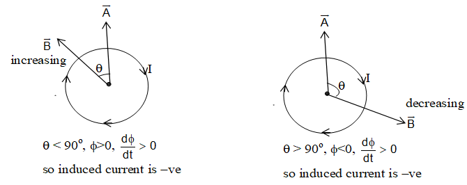
iii) Direction of induced current: The direction of induced current in a loop may be obtained using equations
The steps to decide the direction are as follows
a) Define a positive direction for the area vector .
b) From the direction of and magnetic field , determine sign of and its state of change
c) determine the sing of the induced current. If is positive i.e. flux is increasing, sign of induced current is –ve and vice-versa.
d) Finally determine the direction of induced current using your right hand. Curl the fingers of your right hand , with your right thumb in the direction of , if induced current is +ve, it is in the same direction as your curled fingers and if it is –ve it is in the opposite direction.
Note: To apply lenz’s law, you can remember, RIN or in when loop lies on the plane of paper.
RIN: In RIN
R = stands for right
I = stands for increasing
N = stands for north pole (anti clockwise)

It means, if a loop is placed on the right side of a straight carrying conductor and the current I in conductor is increasing, then induced current in the loop is anticlockwise.
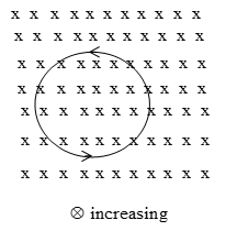
IN: In IN, suppose the magnetic field in the loop is perpendicular to paper inwards () and this field is increasing, then induced current in the loop is anticlockwise.
2. MOTIONAL EMI & INDUCED ELECTRIC FIELD
Dynamic (motional) EMI due to translatory motion
Consider a conducting rod of length l moving with a uniform velocity perpendicular to a uniform magnetic field directed into the plane of the paper. Let the rod be moving to the right as shown in figure. The conducting electrons also move to the right as they are trapped within the rod.
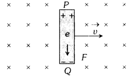
Conducting electrons experience a magnetic force Fm = evB. So they move from P to Q within the rod. The end P of the rod becomes positively charged while end Q becomes negatively charged, hence an electric field is set up within the rod which opposes the further downward movement of electrons, i.e., an equilibrium is reached and in equilibrium
Fe = Fm,
i.e., eE = evB
or E = vB
Induced emf, e = El = BvI
If rod is moving by making an angle with the direction of magnetic field or length, induced emf e = Bvl sin

MOTION OF CONDUCTING ROD ON AN INCLINED PLANE
When conductor starts sliding from the top of an inclined plane as shown figure, it moves perpendicular to its length but at an angle (90 – ) with the direction of magnetic field.
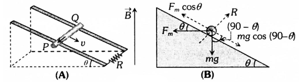
Hence induced emf across the ends of the conductor e = Bv sin(90 – )I = Bvl cos
So induced current (Directed from Q to P).
The forces acting on the bar are shown in following figure. The rod will move down with constant velocity only if
Fm cos = mg cos(90 – ) = mg sin
Bil cos = mg sin
Motional EMI in loop by generated area
If conducting rod moves on two parallel conducting rails as shown figure in following figure then phenomenon of induced emf can also be understood by the concept of generated area (The area swept by conductor in magnetic field during its motion).
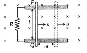
As shown in figure, in time t distance travelled by conductor = vt
Area generated A = lvt. Flux linked with this area = BA = Blvt.
Hence induced emf
1. Induced current:
2. Magnetic force: Conductor PQ experiences a magnetic force in opposite direction of its motion and
3. Power dissipated in moving the conductor: For uniform motion of rod PQ, the rate of doing mechanical work by external agent or mech. power delivered by external source is given as
4. Electrical power: Also electrical power dissipated in resistance or rate of heat dissipation across resistance is given as
(It is clear that Pmech. = Pthermal which is consistent with the principle of conservation of energy.)
5. Motion of conductor rod in a vertical plane: If conducting rod is released from rest (at t = 0) as shown in figure then with rise in its speed (v), induce emf (e), induced current (i), magnetic force (Fm) increases but it’s weight remains constant.
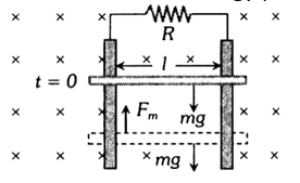
Rod will achieve a constant maximum (terminal) velocity vT if
Fm = mg
So
Special cases
Motion of train and aeroplane in earth’s magnetic field
Induced emf is across the axle of the wheels of the train and it is across the tips of the wing of the aeroplane. It is given by e = Blv where l = length of the axle or distance between the tips of the wings of plane, Bv = vertical component of earth’s magnetic field and v = speed of train or plane.
Motional EMI due to rotational motion
1. CONDUCTING ROD
A conducting rod of length l whose one end is fixed, is rotated about the axis passing through its fixed end and perpendicular to its length with constant angular velocity . Magnetic field (B) is perpendicular to the plane of the paper.
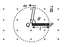
Emf induce across the ends of the rod is
e = BAv,
where = frequency (revolution per sec) and T = Time period.
2. CYCLE WHEEL
In a conducting wheel each spoke of length l is rotating with angular velocity in a given magnetic field as shown in figure.
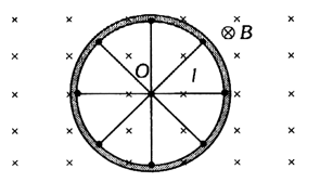
Due to flux cutting each metal spoke becomes identical cell of emf ‘e’ (say), all such identical cells connected in parallel fashion.
Then enet = e (emf of single cell).
Let N be the number of spokes hence
Here enet N°, i.e., total emf does not depends on number of spokes ‘N’.
3. FARADAY COPPER DISC GENERATOR
A metal disc can be assumed to be made of uncountable radial conductors when metal disc rotates in transverse magnetic field.
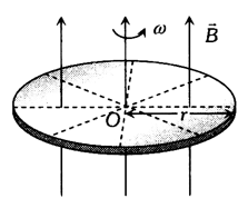
These radial conductors cut away magnetic field lines and because of this flux cutting all become identical cells each of emf ‘e’, where
4. SEMICIRCULAR CONDUCTING LOOP
Consider a semicircular conducting loop (ACD) of radius ‘r’ with centre at O, the plane of loop being in the plane of paper. The loop is now made to rotate with a constant angular velocity , about an axis passing through O and perpendicular to the plane of paper. The effective resistance of the loop is R.
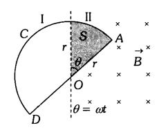
In time t the area swept by the loop in the field, i.e., region II
Flux linked with the rotating loop at time t = BA
Hence induced emf in the loop in magnitude
and induced current
Periodic EMI
Suppose a rectangular coil having N turns is placed initially in a magnetic field such that magnetic field is perpendicular to it’s plane as shown.
– Angular speed
– Frequency of rotation of coil
R – Resistance of coil
For uniform rotational motion with , the flux linked with coil at any time t
– NBA cos = NBA cos t
i.e., = 0 cos t, where
0 = NBA = maximum flux
1. INDUCED EMF IN COIL
Induced emf also changes in periodic manner that’s why this phenomenon called periodic EMI.
, where e0 = emf
amplitude or max. emf = NBA = 0
2. INDUCED CURRENT
At any time t, sint = i0 sin t, where i0 = current amplitude or max. current;
9. Induced Electric fields
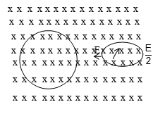
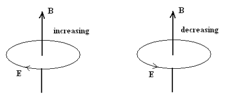
Consider the case shown in the diagram, a circular shaped closed, conducting loop placed inside a Magnetic field B which varies with time. Let us assume that the field increases with time uniformly.

Then by application of Faraday’s law, it is evident that there will an EMF induced in the anti-clockwise orientation given by the expression,
where ‘a’ is the radius of the loop.
the negative sign again indicative of the anti-clockwise orientation of the induced
EMF in the event that the B is increasing with time (and vice-versa).
The conducting loop being a closed one, an induced current will appear in it. Now, the presence of a current indicates the presence of an Electric field E inside the conductor under whose influence the free electrons start moving (current appears). The magnetic field in this case cannot make the electrons move. Hence the conclusion arrived at is that the changing magnetic field (time varying) produces electric fields which cause the current to flow. Since this electric field is not due to charges accumulated, it is non-electrostatic in nature and is called an ‘induced’ electric field (induced by a time varying magnetic field)
Another interesting fact is that field lines representing induced electric fields (as in the above case) are closed curves. They have no starting or terminating points.
By definition of EMF or voltage, , when applied to this particular type of field (induced electric field lines forming closed loops) gives . Hence the total workdone by such a field on a charged particle +q moving around a closed path , which leads to the important conclusion that the induced electric field here, E, is non-conservative in nature. And,
Hence we conclude that the a time-varying magnetic field generates an induced electric field which is non-conservative and non-electrostatic in nature. The field lines for such a field form closed loops and are ‘circular’ in geometry when the magnetic field is symmetrical in space (but varying with time).
NOTE:
a. The electric field produced by stationary charges is called electrostatic field and for this field we know that , hence it is conservative in nature and a path independent potential can be defined for it.
b. A changing magnetic field (in absence of any charges) produces an induced electric field in free space in the form of closed lines of force as shown in the figure below.
c. A charged particle which is free to move in a circular path enclosing a changing magnetic field will experience an increase in its kinetic energy.
d. It is important to note that in case of a non-conservative electric field
Work done by this field around a closed path is not zero. (not true for conservative fields) Lines of force are closed curves and can exist in free space in absence of any charge. For a closed loop in which field B varies with time consider the case as shown below:
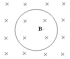
In the above figure shows a ring kept in a time-varying magnetic field B directed into the plane of the paper. Consider the case when B is increasing with time:
Since the increase in B into the plane of paper is causing the current in the ring, the direction of induced emf/current must be such that it must causes magnetic field (due to the current induced) to increase in the opposite direction (which is out of the plane of the paper).
This direction of induced current can be found by using ‘right hand thumb rule’ according to which if one holds the conductor in one’s right hand with the fingers curled in the direction of the induced current, with the thumb stretched as shown in the figure then the direction in which the thumb points should ‘oppose’ the change in flux that is taking place due to the external magnetic field lines varying with time.
NOTE:
a. In case of electromagnetic induction an emf, always exists whether circuit is closed or open but the current will exist only if the circuit is closed. If the total resistance of the circuit is R then the induced current is given by
b. As . Therefore the total charge that flows through a given circuit when the magnetic flux through it changes from to can be calculated directly as
i.e. the charge flowing through a conducting loop due to electro-magnetic induction is independent of time in which the flux changes or independent of the variation of induced EMF and current with time.
3. INDUCTANCE, SELF INDUCTION & MUTUAL INDUCTION
1. INDUCTANCE
(1) Inductance is that property of electrical circuits which opposes any change in the current in the circuit.
(2) Inductance is inherent property of electrical circuits. It will always be found in an electrical circuit whether we want it or not.
(3) A straight wire carrying current with no iron part in the circuit will have lesser value of inductance.
(4) Inductance is analogous to inertia in mechanics, because inductance of an electrical circuit opposes any change of current in the circuit.
2. Self Induction
When a current is flowed in a closed conducting loop, it produces a magnetic filed. This magnetic field has its flux through the area bounded by the loop. If the current change with time, the flux through the loop changes and hence an emf is induced in the loop. This process is called self induction. The name is so called because the source of this induced emf is the change of current in the same circuit. The self induction can be defined as the property of a coil by virtue of which it opposes the growth or decay of the current flowing through it.
The magnetic field at any point due to a current is proportional to the current. The magnetic flux through the area bounded by a current-carrying loop is proportional to the current. We can write
B i
where L is a constant depending on the geometrical construction of the loop. This constant is called coefficient of self induction of the loop or self induction of the loop or self inductance.
Also, according to Faraday’s law of EMI, induced emf in the coil is given by
………. (1)
Unit of self inductance: S.I. unit of self inductance is Henry (H)
1H = 1 V-s/A = 1 Wb/A
CGS unit of self inductance is abhenry (1H = 109 abhenry)
Dimensional formula for self induction (L) =
If we have a coil or a solenoid of N turns, the flux through each turn is . If this flux changes an emf is induced in each turn. The net emf induced between the ends of the coil is the sum of all these i.e.
One can compare this with equation (1) to get the inductance.
Inductor
An element of an electric circuit like a tightly wound coil of insulated wire which opposes the change in current flowing through it is called an inductor. The symbol of an inductor in an electric current is shown as follows.
An ideal inductor has high value of self inductance and zero ohmic resistance.
Self inductance of a plane circular coil
Suppose a current of I is flowing through a circular coil of radius r meters. If N is the number of turns in the coil, then magnetic field produced at the centre of the coil
B =
Magnetic flux ’ linked with each turn of the coil is given by
hence total magnetic flux linked with the coil
Thus coefficient of self induction or self inductance of the coil is
Self induction of a long solenoid
Consider a long solenoid having length l, area of cross section A and number of turns per unit length n.
Total number of turns in the solenoid = n l.
If I be the current flowing through the solenoid then magnetic field inside the solenoid is given by
When the solenoid is sufficiently long, the magnetic field produced well within the solenoid is practically uniform and parallel to its axis. Hence magnetic flux linked with each turn of the solenoid
As total number of turns in the solenoid is nI, hence total magnetic flux linked with the solenoid
But = LI
Note:
i) Self induction is also known as inertia of electricity as it opposes the growth or decay of the current in the circuit.
ii) Both during the growth and decay of current in the coil, an opposing induced emf is produced in the coil. The induced emf for this reason is also called as back emf.
iii) Self inductance of solenoid depends upon the nature of the material of the core of the solenoid also. Coefficient of self induction of solenoid wound on magnetic material is given by L = (where r = Relative permeability of magnetic material)
i.e.
a) Self inductance increase with the increase in the number of turns of the coil and vice verse.
b) Self inductance of the coil increases if the air core of the coil is replaced by the iron core.
iv) If two or more coils of inductances L1, L2, ………. Ln are connected in series, then equivalent inductance between A and B is given by
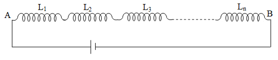
v) If two or more coils of inductances are L1, L2, ………. Ln connected in parallel then equivalent inductance between A and B is given by
If n = 2, then
Energy stored in an Inductor
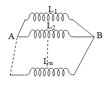
Consider an inductor of inductance L connected across a battery as shown in figure. When current flows through the inductor, an emf is induced in it. This induced emf is given by
……… (i)
-ve sign shows that e opposes the passage of current I in the inductor.
To drive the current through the inductor against the induced emf e, the external voltage is applied. Here external voltage is emf of the battery = -e. Hence from equation (i), we get
Let an small charge dq be driven through the inductor. So the work done by the external voltage is given by
dw = edq =
= dw = LIdI
Total work done to maintain the maximum value of current Io through the inductor is given by
The work done in increasing the current flowing through the inductor is stored as the potential energy (U) in its magnetic field.
Hence energy stored in the inductor is given by
Note
1) Energy stored in the inductor or coil is known as magnetic energy (Um)
Um =
2) Energy stored in the inductor or coil is known as magnetic energy (Vm)
for solenoid
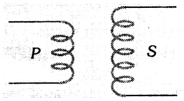
3. Mutual induction
The phenomenon of electromagnetic induction in which, on changing the current in one coil an opposing induced emf or induced current is produced in a neighbouring coil, is known as mutual induction.
The mutual induction between two coils depends upon shape and size of the two coils, their relative orientation, their mutual separation and permeability of the material of the core on which two coils are wounded.
Illustration: Consider two neighbouring coils of wire as shown in fig. A current flowing in coil A produced magnetic field and a magnetic flux through coil B. If the current in coil A changes, the flux through coil B changes as well. According to faraday’s law this induces an emf in coil B. In this way, a change in current in one circuit can induce a current in a second circuit. This phenomena is known as mutual induction. Like the self inductance (L), two circuits has mutual induction (M).
Coefficient of mutual induction
Suppose IA current flowing through the coil A at any instant. It is found that the magnetic flux B linked with the coil B that instant will be directly proportional to the current passing through coil A at that instant i.e.
where M is called coefficient of mutual induction or simply mutual inductance of the two coils. The induced emf produced in the coil B due to changing magnetic flux is given by
SI unit of mutual inductance is also Henry (H).
Mutual inductance between two long solenoids
Consider two air-cored solenoid S1 and S2 of the same length solenoid S2 surrounds solenoid S1 completely as shown in figure. The two solenoids are so closely wound that they have the same area of cross-section A. Let N1 and N2 be the total number of turns S1 and S2 respectively. Mutual inductance at S2 w.r.t. S1 (M21).
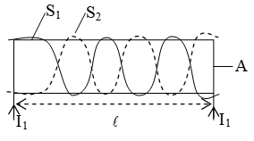
The magnetic field B1 inside solenoid S1 due to current I1 through it is given by
Since the solenoids are closely wound, the magnetic field inside solenoid S2 is also B1.
Magnetic flux linked with each turn of solenoid S2 is
2 = B1 area of each turn = B1A
Magnetic flux linked with N2 turn of solenoid S2 is = N22
Now =
………… (i)
Mutual inductance of S1 w.r.to S2 (M12). The magnetic field B2 inside solenoid S2 due to current I2 through it is given by
Since the solenoids are closely wound, the magnetic field inside solenoid S1 is also B2.
Magnetic flux linked with each turn of S1 is
1 = B2 area of each turn = B2 A
=
Magnetic flux linked with N1 turn of solenoid S1 is
=
Now ……… (ii)
From equation (i) and (ii) we have
Thus the mutual inductance between the two coils is the same no matter which of the two coils carries the current. Therefore no subcriples are needed.
Coefficient of coupling (K)
Coefficient of coupling K of two coils is a measure of the coupling of the two coils and is given by
Where L1 and L2 are the coefficients of self induction of the two coils and M is the coefficient of mutual induction of the two coils.
= 8.88 10-4 Weber
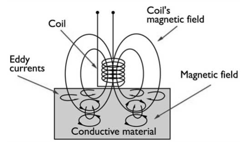
4. Eddy current
When a changing magnetic flux is applied to a bulk piece of conducting material then circulating currents called eddy currents are induced in the material. Because the resistance of the bulk conductor is usually low, eddy currents often have large magnitudes and heat up the conductor.
1. These are circulating currents like eddies in water.
2. Experimental concept given by Focault hence named “Focault current”.
3. The production of eddy currents in a metallic block leads to the loss of electric energy in the form of heat.
4. By lamination, slotting processes the resistance path for circulation of eddy current increases, resulting in to weakening them and also reducing losses cause by them.
Application of eddy currents
Though most of the times eddy currents are undesirable, but they find some useful applications as enumerated below.
(i) Dead-beat galvanometer: A dead beat galvanometer means one whose pointer comes to rest in the final equilibrium position immediately without any oscillation about the equilibrium position when a current is passed in its coil.
This is achieved by winding the coil on a metallic frame. The large eddy currents induced in the frame provide electromagnetic damping.
(ii) Electric-brakes: When the train is running its wheel is moving in air and when the train is to be stopped by electric breaks the wheel is made to move in a field created by electromagnet. Eddy currents induced in the wheels due to the changing flux oppose the cause and stop the train.
(iii) Induction furnace: Joule’s heat causes the melting of a metal piece placed in a rapidly changing magnetic field.
(iv) Speedometer: In the speedometer of an automobile, a magnet is geared to the main shaft of the vehicle and it rotates according to the speed of the vehicle. The magnet is mounted in an aluminium cylinder with the help of hair springs. When the magnet rotates, it produces eddy currents in the drum and drags it through an angle, which indicates the speed of the vehicle on a calibrated scale.
(v) Energy meter: In energy meters, the armature coil carries a metallic aluminium disc which rotates between the poles of a pair of permanent horse shoe magnets. As the armature rotates, the current induced in the disc tends to oppose the motion of the armature coil. Due to this braking effect, deflection is proportional to the energy consumed.
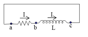
4. GROWTH AND DECAY OF CURRENT IN LR- CIRCUIT,
LC- OSCILLATION & EDDY CURRENT
Growth and decay of current in an LR circuit
Growth of current
Let us consider a circuit consisting of a battery of emf E, a coil of self inductance L, a resistance R and switch S1 and S2. Initially, the switches are open and there is no current in the circuit. At t = 0, the switch S1 is closed and the circuit is completed. As the current increases in the inductors.
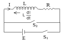
A self-induced emf is produced. Applying Kirchhoff’s loop law we have
Integrating both sides
At t = 0, switch is open I = 0.
Put value of C in equation (1)
The constant had dimension of time and is called time constant of the LR circuit writing and . Eqn (ii) becomes
= 63% of the maximum current fig(a) shows the plot of the current versus time.
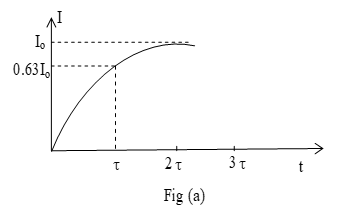
The current gradually rises from t = 0 and attains the maximum value Io after infinity time. At t= the current
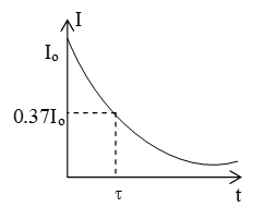
Decay of current
Now suppose switch S1 in the circuit shown in figure has been closed for a long time and the current has reached its steady state value Io. We close switch S2 at time t=0 and a same time we should open switch S1 to by pass the battery. The current through L and R does not instantaneously go to zero but decays exponentially. To apply kirchhoff’s loop rule and to find current in the circuit at time t, let us drawn the circuit once more. Applying loop rule we have
Integrating both sides
…….. (i)
At t = 0, switch S2 is closed and S1 open I = Io
logIo = +C
Put value of C in equation (i) log I =
logI – logIo =
where is time constant
Special cases
Case (i): If t = 0, I = Io
Case(ii): If t = , I =
Case (iii) If t = , I = = 0.37
= 37% of its original value
The I-t graph is as shown in figure.
……… (ii)
Note
that the final current (maximum current) Io does not depend on the inductance L, it is the same as it would be if the resistance R alone were connected to the source with emf E.
Let us have an insight into the behaviour of an L-R circuit from energy considerations.
The instantaneous rate at which the source delivers energy to the circuit (P = Ei) is equal to the instantaneous rate at which energy is dissipated in the resistor (=I2R) plus the rate at which energy is stored in the inductor .
Thus,
2. Growth and Decay of Current in LR – Circuit
i) The value of current of any instant of time t after closing the circuit (i.e., during the rising of current) is given by where steady state current.
ii) The value of current at any instant of time t after opening from the already state condition (i.e., during the decaying of current) is given by
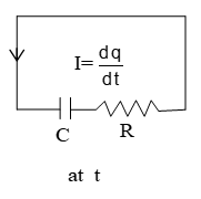
3. Growth and decay of charge in C-R circuit growth of charge
Let us consider a circuit consisting of a battery of emf E, a capacitor of capacitance C a resistance R and switch S2 and S2. Initially the switches are open and three is no current in the circuit. At t=0, the switch S1 is closed and the circuit is completed. Let at any instant during the growth of charge on the capacitor, I be the charging current and of the charge on the capacitor.
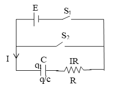
Applying Kirchhoff’s loop law, we have
Integrating both sides
……….. (i)
At t = 0, q = 0
Put the value of K in equation (i)
………. (ii)
The constant CR has dimension of time and is called time constant of the CR circuit writing RC=tc and EC = qo equation (ii) becomes
……… (iii)
Differentiate w.r.to t
where ………(iv)
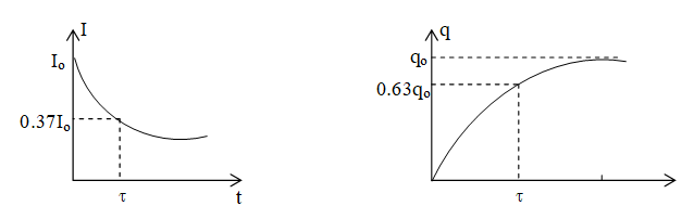
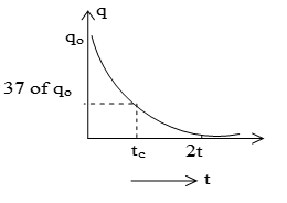
figure (a) shows the plot of charge and current versus time. The charge gradually rises from t=0 and attains the maximum value qo after infinity time. The current gradually decreases from its maximum value Io to zero.
Special cases
Case (i) If t=0, q=0, I=Io
Case (ii) If t = tc q = 63% of qo
I = 37% of Io
Case (iii) If t = q = qo, I=0. It is also called the steady state charge or maximum charge.
4. Decay of charge
Now suppose switch S1 in the circuit shown in figure has been closed for along time and the charge has reached its steady state value qo. We close switch S2 at time t=0 and at same time we should open switch S1 to bypass the battery. The charge through C does not instantaneously go to zero but decay exponentially. To apply Kirchoff’s loop rule to find the current (charge) in the circuit at time t, let us draw the circuit once more.
Applying loop rule we have
Integrating both sides we get
……. (i)
at t = 0, q = qo
logqo = 0 + K
K = logqo
Put the value of K in equation (i)
Logq =
……… (ii)
Above equations gives the value of charge q at any instant during the discharging of the capacitor through R. This equation shows that charge on the capacitor decays exponentially becoming zero asymptotically at t = . A graph showing the decay of charge with respect to time
Note:
i) A capacitor offers zero resistance when it is uncharged i.e. it can be assumed as short circuited and it offer infinite resistance when it is fully charged i.e. no current flow through
ii) To find the equivalent time constant of a circuit, following step is follow.
a) Short circuit the battery
b) Find equivalent resistance across capacitor (say it Rnet)
5. APPLICATION OF EMI (MOTOR, DYNAMO, TRANSFORMER, ETC)
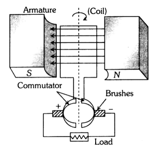
1. Dc motor
It is an electrical machine which converts electrical energy into mechanical energy.
Principle
It is based on the fact that a current carrying coil placed in the magnetic field experiences a torque. This torque rotates the coil.
Construction
It consists of the following components (see Figure):
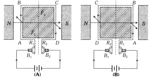
ABCD = Armature coil, S1, S2 = split ring comutators
B1, B2 = Carbon brushes, N, S = Strong magnetic poles
Working
Force on any arm of the coil is given by . From figure, force on AB will be perpendicular to plane of the paper and pointing inwards. Force on CD will be equal and opposite. So coil rotates in clockwise sense when viewed from top in figure. The current in AB reverses due to commutation keeping the force on AB and CD in such a direction that the coil continues to rotate in the same direction.
Back Emf In Motor
Due to the rotation of armature coil in magnetic field a back emf is induced in the circuit. It is given by e = E-iR
Back emf directly depends upon the angular velocity of armature and magnetic field B. But for constant magnetic field B, value of back emf e, e or e = k (e = NBA sint)
Current In The Motor
,
When motor is just switched on = 0 so e = 0. Hence maximum and at full speed, is maximum so back emf e is maximum and i is minimum. Thus, maximum current is drawn when the motor is just switched on which decreases when motor attains the speed.
Motor Starter
At the time of start a large current flows through the motor which may burn it out. Hence a starter is used for starting a dc motor safely. Its function is to introduce a suitable resistance in the circuit at the time of starting of the motor. This resistance decreases gradually and reduces to zero when the motor runs at full speed.
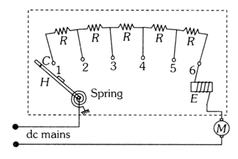
The value of starting resistance is maximum at time t = 0 and its value is controlled by spring and electromagnetic system and is made to zero when the motor attains its safe speed.
Mechanical Power And Efficiency Of Dc Motor
Uses Of Dc Motors
They are used in electric locomotives, electric ears, rolling mills, electric cranes, electric lifts, dc drills, fans and blowers, centrifugal pumps and air compressors, etc.
2. Ac generator/alternator/dynamo
An electrical machine used to convert mechanical energy into electrical energy is known as ac generator/alternator.
Principle It works on the principle of electromagnetic induction, i.e., when a coil is rotated in uniform magnetic field, an induced emf is produced in it.
Construction
The main components of ac generator are
1. Armature: Armature coil (ABCD) consists of large number of turns of insulated copper wire wound over a soft iron core.
2. Strong field magnet: A strong permanent magnet or an electromagnet whose poles (N and S) are cylindrical in shape acts as a field magnet. The armature coil rotates between the pole pieces of the field magnet. The uniform magnetic field provided by the field magnet is perpendicular to the axis of rotation of the coil.
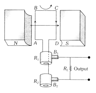
3. Slip rings: The two ends of the armature coil are connected to two brass slip rings R1, and R2. These rings rotate along with the armature coil.
4. Brushes: Two carbon brushes (B1 and B2) are pressed against the slip rings. The brushes are fixed while slip rings rotate along with the armature. These brushes are connected to the load through which the output is obtained.
Working
When the armature coil ABCD rotates in the magnetic field provided by the strong field magnet, it cuts the magnetic lines of force. Thus the magnetic flux linked with the coil changes and hence induced emf is set up in the coil. The direction of the induced emf or the current in the coil is determined by the Fleming’s right hand rule.
The current flows out through the brush B1 in one direction of half of the revolution and through the brush B2 in the next half revolution in the reverse direction. This process is repeated. Therefore, emf produced is of alternating nature.
3. Dc generator
If the current produced by the generator is direct current, then the generator is called dc generator. DC generator consists of (i) Armature (coil) (ii) Magnet (iii) Commutator (iv) Brushes
In DC generator commutator is used in place of slip rings. The commutator rotates along with the coil so that in every cycle when direction of ‘e’ reverses, the commutator also reverses or makes contact with the other brush so that in the external load the current remains in the same direction giving DC.
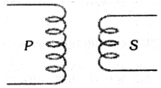
4. Transformer
It is a device which raises or lowers the voltage in ac circuits through mutual induction.
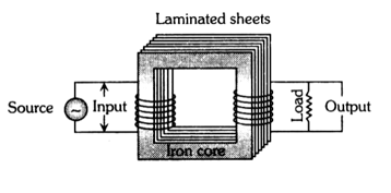
It consists of two coils wound on the same core. The alternating current passing through the primary creates a continuously changing flux through the core. This changing flux induces an alternating emf in the secondary.
1. Transformer works on ac only and never on dc.
2. It can increase or decrease either voltage or current but not both simultaneously.
3. Transformer does not change the frequency of input ac.
4. There is no electrical connection between the winding but they are linked magnetically.
5. Effective resistance between primary and secondary winding is infinite.
6. The flux per turn of each coil must be same, i.e.,
7. Let Np = number of turns in primary, Ns = number of turns in secondary, VP = applied (input) voltage to primary, Vs = Voltage across secondary (load voltage or output), eP = induced emf in primary ; eS = induced emf in secondary, = flux linked with primary as well as secondary, iP = current in primary; iS = current in secondary (or load current)
As in an ideal transformer there is no loss of power, i.e., Pout = Pin so VSiS = VPiP and VP eP, VP eS.
Hence ; k = Transformation ratio (or turn ratio)
(i) In a transformer Vs and Vp are in opposite phase, i.e., a phase difference of exists between them.
(ii) For this the law of conservation of energy is held valid.
| Types of transformer | |
| Step up transformer | Step down transformer |
|
It increases voltage and decreases current
VS > VP NS > NP ES > EP iS < iP RS > RP k > 1 |
It decreases voltage and increases current
VS < VP NS < NP ES < EP iS > iP RS < RP k < 1 |
8. Efficiency of transformer (): Efficiency is defined as the ratio of output power and input power
i.e.
For an ideal transformer Pout = Pin so n = 100% (But efficiency of practical transformer lies between 70% – 90%) For practical transformer Pin = Pout + Plosses
So
9. Losses in transformer: In transformers some power is always lost due to heating effect, flux leakage, eddy currents, hysteresis and humming.
(i) Cu loss (i2R): When current flows through the transformer windings some power is wasted in the form of heat (H = i2Rt). To minimize this loss, windings are made of thick Cu wires (to reduce resistance).
(ii) Eddy current loss: Some electrical power is wasted in the form of heat due to eddy currents induced in core. To minimize this loss transformer cores are laminated and silicon is added to the core material as it increases the resistivity. The material of the core is then called silicon-iron (steel).
(iii) Hysteresis loss: The alternating current flowing through the coil magnetises and demagnetises the iron core again and again. Therefore, during each cycle of magnetisation some energy is lost due to hysteresis. However, the loss of energy can be minimised by selecting the material of core which has a narrow hysteresis loop. Therefore core of transformer is made of soft iron. Now a days it is made of “Permalloy” (Fe-22%, Ni-78%).
(iv) Magnetic flux leakage: Magnetic flux produced in the primary winding is not completely linked with secondary. Because of this few magnetic lines of force complete their path in air only. To minimize this loss secondary winding is kept inside the primary winding.
(v) Humming losses: Due to the passage of alternating current, the core of the transformer starts vibrating and produces humming sound. Thus, some part (may be very small) of the electrical energy is wasted in the form of humming sounds produced by the vibrating core of the transformer.
10. Uses of transformer: A transformer is used in almost all ac operations, e.g.,
(i) In voltage regulators for TV, refrigerator, computer, air conditioner etc.
(ii) In the induction furnaces.
(iii) Step down transformer is used for welding purposes.
(iv) In the transmission of ac over long distance.
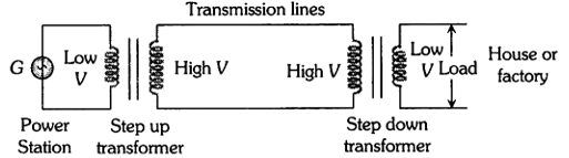
(v) Step down and step up transformers are used in electrical power distribution.
(vi) Audio frequency transformers are used in radiography, television, radio, telephone etc.
(vii) Radio frequency transformers are used in radio communication.
(viii) Transformers are also used in impedance matching.
SOLVED EXAMPLES
Example-1
Consider a uniform magnetic field in a certain region and a ‘square’ surface of dimensions placed in the Y-Z plane as shown in the figure, calculate the magnetic flux through this surface.
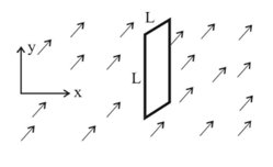
Solution
The magnetic field being uniform and the surface a ‘lamina’, magnetic flux can be calculated by the expression or
Example-2
The magnetic field in a certain region varies linearly with position according to the equation, . Find the magnetic flux through a square frame () placed in the X-Y plane with it’s sides parallel to X and Y axes as shown in the diagram alongside.

Solution
Since the field here is ‘non-uniform’, use the expression .
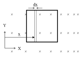
From the diagram below, take , for a differential area element which is a vertical ‘thin strip’ of thickness ‘dx’ and length L as shown, ,
therefore
Taking just the ‘magnitude’ of the flux here,
Example-3
A square loop ACDE of area 40 cm2 and resistance 10 is rotated in a magnetic field =4T through 180o (a) in 0.01 s and 9b) in 0.02 s. Find the magnitude of e, I and q in both the cases.
Solution
Given that A = 40 cm2, R= 10, B = 4T
Let us take the area vector perpendicular to plane of loop inward i.e. = 0o.
Initial flux passing through the loop,
I = BAcos = 44010-4cos0 = 1610-3 Wb.
Flux passing through the loop when it rotated by 180o
=
therefore, change in flux
a) t = 0.015; R = 5
b) t = 0.02 s
Example-4
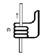
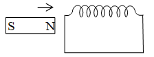
A bar magnet is brought near a solenoid as shown in figure will the solenoid attract or repel the magnet?
Solution
When the magnet is brought near the solenoid, according to lenz’s law, both repel each other.
Example-5
A conducting circular loop is placed in a uniform magnetic field 0.04 T with its plane perpendicular to the magnetic field. The radius of the loop starts shrinking at 2 mm/s. The induced emf in the loop when the radius is 2 cm is
(A) 3.2 V (B) 4.8 V (C) 0.8 V (D) 1.6 V
Solution
Example-6
Two rails of a railway track insulated from each other and the ground are connected to a milli voltmeter. What is the reading of voltmeter, when a train travels with a speed of 180 km/hr along the track. Given that the vertical component of earth’s magnetic field is 0.2 × 10⁻⁴ weber/m2 and the rails are separated by 1 metre
(A) 10–2 volt (B) 10–4 volt (C) 10–3 volt (D) 1 volt
Solution
Example 7
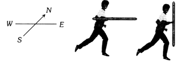
A player with 3 m long iron rod runs towards east with a speed of 30 km/hr. Horizontal component of earth’s magnetic field is 4 x 10⁻⁵ Wb/m2. If he is running with rod in horizontal and vertical positions, then the potential difference induced between the two ends of the rod in two cases will be
(A) Zero in vertical position and 1 × 10⁻³V in horizontal position
(B) 1 × 10⁻³V in vertical position and zero is horizontal position
(C) Zero in both cases
(D) 1 × 10⁻³V in both cases
Solution
If player is running with rod in vertical position towards east, then rod cuts the magnetic field of earth perpendicularly (magnetic field of earth is south to north). Hence Maximum emf induced is
When he is running with rod in horizontal position, no field is cut by the rod, so e = 0.
Example-8
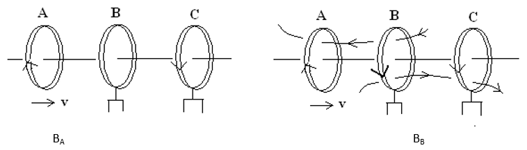
Three identical coils A, B and C are placed with their planes parallel to one another. Coils A and C carry equal currents as shown in the fig. Coils B and C are fixed in position and coil A is moved towards B with uniform motion. Is there any induced current in B? If no, give reason; if yes, mark the direction of induced current in the diagram.
Solution
Due to motion of coil A towards B, the flux linked with B due to A will increase while that due to C will remain constant. So in accordance with Lenz’s law a current will be induced in B which will oppose the change i.e approach of A towards B (which leads to the increase in the flux linked with the B due to A). The direction of flux due to A linked with the B is shown in the fig.(B). Hence the direction of current in coil B has to opposite to that in A. The current in the coil B will produce flux in the direction which is opposite to the flux due to A (opposite currents repel each other).
Example-9
When the current in a coil changes uniformly from 8A to 2A in 3×10⁻² s, the emf induced in the coil is a constant 2 Volts during the 3×10⁻² s. What is the self-inductance of the coil in mH (milliHenry).
Solution
As in case of self-inductance, the magnitude of the induced emf, ,
therefore
Example-10
A solenoid S1 is placed inside another solenoid S2. The radii of inner and the outer solenoids are R1 and R2 respectively and the number of turns per unit length are n1 and n2 respectively. Consider a length L of the solenoid. Calculate the mutual inductance them.
Solution
Suppose a current i is passed through the inner solenoid S1. A magnetic field is produced inside S1 whereas the field outside it is zero. The flux through each turn of S2 is
The total flux through all the turns in a length L of S2 is
Thus,
Example-11
A coil of resistance 40 and inductance 0.5H is switched to dc 100 volt supply. Calculate the rate of increase of current.
a) at the instant of closing the switch and
b) after one time constant
c) Find the steady state current in the circuit.
Solution
Given that
R = 40, L = 0.5H, E=100 V
Steady state current
Time constant
This is curve of growth in an L circuit. Hence, current at time t is given by
Differentiating w.r.to t
a) at t = 0
b) At
Steady state current I = Io = 2.5 A
Example-12
An e.m.f. of 15 volt is applied in a circuit containing 5 henry inductance and 10 ohm resistance. The ratio of the currents at time t = and at t = 1 second is
(A) (B) (C) 1 – e–1 (D) e–1
Solution
i = i0(1 – e–Rt/L)
(Steady current) (when t = ) i = (1 – e–) = = 1.5
i1 = 1.5(1 – e–R/L) = 1.5(1 – e–2)
Example-13
An inductor of 2 henry and a resistance of 10 ohms are connected in series with a battery of 5 volts. The initial rate of change of current is
(A) 0.5 amp/sec (B) 2.0 amp/sec (C) 2.5 amp/sec (D) 0.25 amp/sec
Solution
Initially, = 2.5 amp/sec.
Example-14
An AC generator of 220 V having internal resistance r = 10 and external resistance R = 100. What is the power developed in the external circuit?
(A) 484 W (B) 400 W (C) 441 W (D) 369 W
Solution
V = 200V; r = 10
R’ = 10 + 100 = 110
P = I2R = 4 × 100 = 400 W
Example-15
A current of 5 A is flowing at 220 V in the primary coil of a transformer. If the voltage produced in the secondary coil is 2200 V and 50% of power is lost, then the current in the secondary will be
(A) 0.25 A (B) 0.5 A (C) 2.5 A (D) 5 A
Solution Given the power output is 50% of the input power, is iSVS = (1/2)iPVP; Also given iP = 5A, VP = 220V and VS = 2200V
.