


1. CATHODE RAYS AND ELECTRONS
Introduction
The word ‘atom’ has been derived from Greek word which literally means indivisible. In 1803, ‘Dalton’ put forward his atomic theory according to which ‘atom’ was indivisible neutral particle. But Dalton’s model of atom could not explain how electricity could interact with matter. Michael Faraday studied the passage of electricity through liquid solutions. His famous laws of electrolysis established that matter is electrical in nature. In 1870 William Crookes did experiments about discharge of electricity through gases which led to the discovery of cathode rays. The cathode rays consist of stream of negatively charged particles. The next step in the study of electric nature of matter was made by J.J. Thomson in 1897. His studies on the electrical discharge through gases at low pressure established that an atom was divisible.
It is now well known that one of the particles which is found as a constituent of all matter and which seems to be the fundamental particle in the universe is the electron. Electrons existing in different substances are alike i.e. they have the same charge and mass. The most important aspect in the study of electron is to determine the charge and mass associated with it because these constants appear in many formulas in Atomic Physics. To begin with, we shall see how the discovery of this sub-atomic particle was made. Then we shall focus on the methods of determining the charge and mass of this fundamental particle.
Discovery of electron
The study of discharge of electricity through gases at low pressures, by J.J. Thomson and Sir William Crookes resulted in the discovery of cathode rays. When the pressure of the gas in a discharge tube is lowered, and sufficiently high potential of the order of 15 to 20 KV is applied between the electrodes, at a certain stage the Crooke’s dark space fills the whole length of the tube. At still lower pressure (below 0.1 mm of Hg), a fluorescent glow appear on the walls of the tube, opposite the cathode (C).
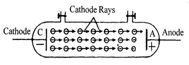
This shows that some invisible particles or radiation are coming out from cathode and travelling the length of the tube anode (A). These invisible streams of particles or radiation are called cathode rays.
Properties of Cathode rays
Some important properties of cathode rays are
i) Cathode rays travel in straight lines and cast sharp shadow of the object placed in their path.
ii) Cathodes rays are emitted normally from the surface of the cathode.
iii) Cathode rays exert mechanical force on the objects on which they fall.
iv) Cathode rays produced heat when they fall on matter.
v) Cathode rays are deflected by electric field. The cathode rays are deflected towards the positive plate showing that they are negatively charged particles.
vi) Cathode rays are deflected by magnetic field.
vii) Cathode rays ionize the gas through which they pass
viii) They travel with high speed ranging from to th of the velocity of light. (cathode rays are not electromagnetic wave)
ix) They can affect a photo graphic film.
x) The cathode rays are independent of the nature of the gas or electrodes used in the discharge tube.
xi) When fast moving cathode rays are stopped by a metal of high atomic number, X-rays are produced.
Note:
i) A gas under ordinary conditions of pressure is an insulator and cannot conduct current. If gas pressure is low, it is possible to cause conduction in the gas.
ii) The passage of electric current through a gas at a low pressure is called electric discharge.
iii) As the pressure of the air or gas inside the discharge tube is gradually reduced, the following observations were made:
a) When the pressure inside the tube is above 10 mm of mercury, no discharge passes through the gas.
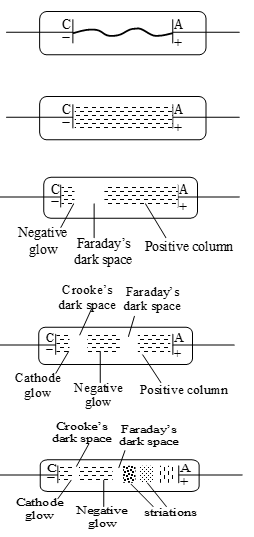
b) When the pressure is reduced to about 10 mm of Hg, the discharge begins to pass between the electrodes with cracking sound. This discharge follows a zig-zag path as shown in the figure.
c) When the pressure inside the tube is reduced to about 4 mm of hg, the discharge broadens out and whole tube is filled with bright light which is called positive column or Geissler’s discharge. The colour of the discharge depends upon the nature of gas in discharge tube.
d) When the pressure of gas becomes 1.65 mm of mercury, light of sky-blue colour is produced at the cathode, called as negative glow. At same time, the positive column contracts towards the anode producing a dark gap between negative glow and positive glow known as Faraday’s dark space.
e) When the pressure of the gas is reduced to 0.8 mm, the negative glow is detached from the cathode. This creates a dark space between the cathode and negative glow, known as Crook’s dark space. Moreover, the length of positive column is further reduced and a very small glow is produced at cathode, called as cathode glow.
f) When the pressure becomes approximately 0.37 mm of mercury, the positive column breaks into striations (illumination strips) and there is no light between negative glow and these strips.
g) When the pressure becomes 0.02 mm of Hg, the positive column, the Faraday’s dark space etc vanish at anode and the tube is completely occupied by Crook’s dark space.
h) When pressure drops to nearly mm of Hg, discharge stops through the gas.
Cause of coloured discharge
The electrons (i.e. cathode rays) moving from cathode to anode collide with atoms of the gas in the tube. As a result, the atoms get excited, when these atoms de- excite (i.e. return to their ground energy state) they emit colours characteristic of their structure. As the pressure in the tube is reduced, the density of the gas decreases. In other words, the gas is rarefied and there are rare collisions of electrons and atoms of the gas. Consequently the atoms of the gas remain unexcited and tube at this stage blacks out.
Determination of specific charge (charge/mass) of electron by J.J. Thomson’s method:
In 1897, J.J. Thomson made use of cross field to determine the e/m of an electron.
Principle: This method is based on the principle that if an electron beam is subjected to cross field in such a way that force exerted on the beam by each field is of same magnitude, then beam will go undeflected.
Construction: Figure shows the schematic diagram of the apparatus. The apparatus consists of a discharge tube in which electrons are emitted from hot filament which acts as cathode (F) and the anode is a plate ‘A’ with a very narrow axial hole. A potential difference of ‘V’ is maintained between cathode filament and anode plate, so that the electrons emitted from hot filament F are accelerated towards anode and emerge out of the anode plate as a narrow beam. There are two parallel aluminium plates P1 and P2 between which high tension battery is connected to maintain uniform electric field E in the plane of the paper from P1 to P2. A magnetic field B applied perpendicular to the plane of the paper. The strengths of the electric fields are adjusted so that the upward deflection of the beam of electron due to the electric field was completely cancelled by the downward deflection by the magnetic field. When there are no electric and magnetic fields the electron beam strikes the screen S at P. If only magnetic field of induction B is applied, the electron beam experiences a magnetic force of magnitude.
∴ ….. (i)
where v is velocity of electron and e is the charge of the electron. According to Fleming left hand rule, the electron beam strikes the screen at N. If only electric field E is applied the electron beam experience an upward electric force of magnitude
Fe = eE ….. (ii)
and strikes the screen at M. If both the fields are simultaneously applied the electron beam strikes the screen at P1 as the magnitude of the forces due to electric field and magnetic field is made equal. Therefore, we get
eE = Bev
v = …… (iii)
Since the electron motion is unaffected by the fields, then in equation (iii) the velocity v imparted to the electron is by the voltage V applied between the cathode (C) and anode (A).
Then work done when charge ‘e’ falls through a P.D. V is equal to its kinetic energy.
Hence
substituting the value of v from equation (iii), we get
Thus of cathode ray particle i.e. electron can be determined and its value is found to . The ratio of is independent of the nature of cathode, anode, applied voltage and material of gas present in discharge tube.
Determination of charge on electron – Millikan’s oil drop experiment
The charge on an electron was determined experimentally by R.A. Millikan in 1913.
Principle: The principle of Millikan’s experiment is to measure the terminal velocity of the charged oil droplets:
i) Under the action of gravity alone and (ii) under the combined action of gravity and electric field opposed to gravity. Knowing the terminal velocities under these conditions we can easily find the charge on each droplet.
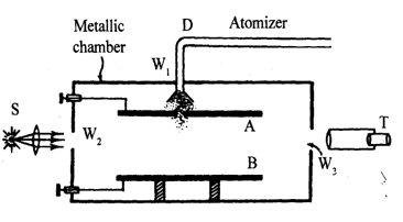
Millikan’s apparatus is shown in figure. The apparatus consists of two accurately parallel horizontal metal plates A and B. An oil is sprayed in fine droplets from an atomizer held above the upper plate and few droplets are allowed to fall through small hole H in the upper plate. A beam of light is directed between the upper plate A and the lower plate B and a telescope T step with its axis transverse to the light beam. The oil droplets, which are illuminated by the light beam, appear like bright tiny spots when viewed through the telescope. The droplets fall slowly under the combined influence of their weight. The bouyant force of the air and force of viscosity opposing their motion. When no electric field is applied the oil drops move down to gravity.
Effective weight of drop = True weight – Buoyancy acting upward
………. (1)
where r is radius of the drop, is density of oil and is density of air.
The upward viscous force on the oil drop is [ = coefficient of viscosity]
When the droplet acquires terminal velocity v1, then effective weight of drop = viscous force
…….. (iii)
…….. (iv)
A strong electric field is applied between the plates in such a direction that force on the negatively charged oil droplet due to electric field acts in the vertically upward direction. Now the droplet starts moving upward and soon attain a terminal velocity v2 (upward). In this case viscous force is acting down ward for equilibrium
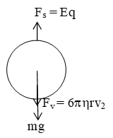
= effective weight + Fv
Eq =
From equation (iii)
q =
q =
where V is applied P.D. between plates and d is plate separation.
Note:
i) If the same drop moves up with terminal velocity after picking up additional charge due to x-rays, the difference in the charge possessed by the drop is proportional to
ii) When the charged oil drop is at rest in uniform electric field, then
and (V=potential difference)
if the same oil drop is kept stationary by allowing it to pick up different charges by ionizing the space between the plates continuously, then
Importance of Millikan oil drop method
1) The charge ‘e’ on the electron is the smallest possible charge.
2) The total charge on a body can be integral multiple of e or q = ne where n = 1,2,3…..n. That means charge is quantized.
3) The specific charge of an electron was determined by J.J. Thomson as .
Effect of electric field on charged particle
When a charged particle of mass m having charge q moving with velocity is subjected to a uniform electric field of intensity , then
a) Force experienced by the particle is F = Eq
b) Acceleration of the charged particle is a =
c) Magnitude of the force is independent of
d) If q is positive, acts in the direction of and if q is negative, acts opposite to the direction of .
e) If is parallel or antiparallel to , the charged particle follows a straight line path in the electric field.
f) If the angle between and is other than 00 and 1800, the charged particle follows a parabolic path in the electric field.
g) If the electric field acts through distance ‘l’ in the direction of motion of charge, time taken by it to cross the electric field is t = l/v
h) If the electric field acts perpendicular to the initial direction of motion of charge, displacement of that particle parallel to the field is (Parabolic path)
i) Deflection of charged particles of same energy in an electric field
j) A uniform electric field can be produced between two parallel plates. Intensity of the field is E = V/d, where V is potential difference between the plates and d is the plate separation.
k) A charged sphere of mass m having a charge q is balanced in a uniform electric field acting vertically up. Then Eq = mg
Specific charge
j) If the field is reversed in this case the sphere moves down with an acceleration 2g
l) If the field is turned through 900, sphere moves with an acceleration along a direction making an angle 450 to the field direction.
m) If another sphere of same material having the same charge but double the radius is to be balanced, the strength of field required is 8E (since weight of the sphere is 8 mg). For this the plate separation may be reduced to keeping the potential difference same or potential difference can be increased to 8 times keeping the same separation.
n) If the plate separation is reduced to half the charged sphere which was balanced initially now it moves up with an acceleration ‘g’.
Effect of magnetic field on charged particle
When a charged particle of mass m, having a charge q, moving with a velocity is subjected to a uniform magnetic field of magnetic induction , then
a) Force experienced by the particle is .
b) is parallel or antiparallel to , then the force on the particle is zero. Here velocity of the particle remains unchanged.
c) The force on the charged particle is maximum if is perpendicular to . This maximum force is equal to F=Bqv This force provides the required centripetal force i.e.
Here ‘r’ is radius of the circular path described by the charged particle.
d) If the charge enters at right angles to the field, time period of its rotation is
e) Frequency of rotation
f) Momentum of particle = Bqr
g) Kinetic energy of the particle =
h) The speed, magnitude of linear momentum and kinetic energy of the charged particle do not change while moving through the magnetic field.
i) When the charged particle enters at right angles to the magnetic field, its acceleration is ‘a’ = .
j) If the magnetic field acts through a distance ‘d’ time taken by it to cross the field is t = l/v.
k) Displacement of the charged particle due to magnetic field is
l) If the charged particle is moving at an angle θ, where θ≠0 or 1800 or 900, the path of particle in the magnetic field is helical.
m) When a charged particle enters into a region having uniform electric and magnetic fields, then force acting on it is . This is known as Lorentz force.
Determination of specific charge of an electron (J.J. Thomson’s Method)
a) In this method, fine beam of electrons is made to pass through a crossed electric field and magnetic field applied each perpendicular to the direction of motion i.e.
b) In the beginning the strengths of the fields is so adjusted that the electron beam goes undeviated while passing through the fields. Then force on electron due to electric field is equal and opposite to the force due to magnetic field.
i.e Ee = Bev v = E/B
c) If V0 is the voltage applied between the cathode and anode to accelerate the electron beam, then
d) If the electric field is switched off and only the magnetic field is applied, the electron beam will be bent into an arc of a circle of radius ‘r’.
e) If the magnetic field is switched off and only the electric field is applied, deflection of the electron in the electric field is given by
Here l is the distance through which the electric field is applied.
f) The value of of electron was found to be 1.7589 ⨯ 1011 CKg-1.
If the speed of electron increases, its specific charge decreases.
2. ELECTRON EMISSION, PHOTOELECTRIC EFFECT, ITS PARAMETERS AND PHOTOELECTRIC CELLS
Electron emission
The liberation of electrons from the surface of a metal is known as electron emission. If a piece of metal is investigated at room temperature, the free electrons of the metal may transfer from one atom to another within the metal but they cannot leave the metal surface, because at the surface of the metal, a free electron encounters forces that prevents it to leave the metal. In other words the metallic surface offers a barrier to free electrons is known as surface barrier. However, if sufficient energy is given to the free electrons, their KE increases and thus the electrons will cross over the surface barrier to leave the metal.
Work function ()
The minimum energy required by an electron to just escape (i.e. with zero velocity) from metal’s surface is called work function () of the metal. The work function of pure metals varies (roughly) from 2 eV to 6 eV. Its value depends upon the nature of the metal, its purity and the conditions of the surface. We select those metals for electron emission, which have low work function.
Types of electron emission
The electron emission from the surface of a metal is possible only if sufficient additional energy (equal to work function of the metal) is supplied from some external source. There are following four principle methods of obtaining electron emission from the surface of a metal.
i) Thermionic emission
(ii) Field emission
(iii) Photoelectric emission
(iv) Secondary emission
i) Thermionic emission
It is the phenomenon of emission of electrons from the surface of metals when heated suitably. The electrons so emitted are called thermions or thermal electrons. The number of electrons emitted depends upon the temperature at which the metal is heated. The metal is called an emitter, filament or cathode.
ii) Field emission or cold cathode emission
It is the phenomenon of emission of electrons from the surface of a metal under the application of a strong electric field. When a very strong electric field (=108 V/m) is applied to metal it emits electron. The number of electrons emitted depends on the strength of field applied.
iii) Photoelectric emission
It is the phenomenon of emission of electron from the surface of metal when light radiations of suitable frequency fall on it. Here the energy to the free electrons for their emission is being supplied by light photons. The emitted electrons are called photoelectrons. The number of electrons emitted depends upon the intensity of incident light.
iv) A secondary emission
It is the phenomenon of emission of electrons from the surface of metal in large number when fast moving electrons (called primary electrons) strike the metal surface.
Photoelectric effect
The emission of electrons from a metal plate when illuminated by light or any radiation of suitable wave length is called ‘photo electric emission’. The emitted electrons are called photo electrons and the phenomenon is called photoelectric effect. The metal which emits electrons is known as photo metal. For example Zn, Mg, Li, Na, K. In photo electric effect light energy is converted into electrical energy. Photo electric effect proves the particle nature of light.
The phenomenon of photoelectric effect was discovered by Hertz.
Experimental study of photoelectric effect:
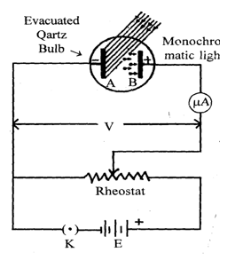
A simple experimental arrangement to study photo electric effect is shown in figure. The apparatus consists of an evacuated quartz tube having a photosensitive plate A called emitter and another plate B called collector. The plate A is mounted before a window also made of quartz through which light radiation is incident on it. The plate A is connected to the –ve terminal of a potential divider while the plate B is connected to the +ve terminal through a micro ammeter. In the absence of any radiation on plate, there is no flow of current and hence there is no deflection in ammeter. But when monochromatic radiation is allowed to fall on plate A, current starts flowing in the circuit which is indicated by ammeter. The current is known as photo electric current.
a) Study of effect of potential on photo electric current:
i) When light of suitable frequency fall on the metallic plate A, photoelectrons are emitted. These electrons get accelerated towards the plate B and constitute the current called photoelectric current. For fixed frequency and intensity of incident light this photo electric current increases with the increase in applied positive potential of plate B. When all the photo electrons are emitted by plate A, the photoelectric current attains maximum value known as saturation current. This saturation current will not increase with the increase positive potential of plate B. Now the potential of plate B is decreased such that it attains negative potential with reference to plate A. The negative potential applied to plate B is increased to a certain value Vo, for which no photo-electrons reach the plate B that is photo electric current is zero. The minimum negative potential (Vo) applied to anode for which photoelectric current becomes zero is called cut-off potential or stopping potential.
At this state, the maximum kinetic energy of photo-electron must be equal to eVo
i.e.
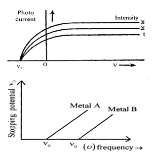
If the experiment is repeated with different intensities of monochromatic light, it is found that as intensity of incident light is increased the saturation current value increases but the stopping potential is found to be same. Variation of photoelectric current with varying potential of pate B is shown in figure.
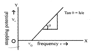
ii) Study of effect of frequency of incident radiation on stopping potential for a given emitting surface: We determine the stopping potential at various frequencies of incident radiation keeping intensity of the radiation constant. The variation of stopping potential with frequency for two metals has been shown in figure.
It shows that there is a minimum value of frequency () of incident light below which photoelectric emission is not possible. This frequency is known as threshold frequency or cut off frequency ().
The value of threshold frequency depends upon the nature of the substance emitting the photo-electrons i.e. . Intensity of incident light is kept constant but the frequency is changed so that in each case the saturation current is exactly the same.
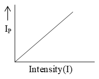
Effect of intensity of incident light on the photoelectric current:
Let a constant P.D. be applied across the anode and the cathode. The photoelectric current (IP) constituted by these photoelectrons is measured with micro-ammeter. As the intensity of the incident light increases, more and more photoelectrons are emitted by cathode and hence photoelectric current increases linearly i.e. . The variation of photoelectric current with the intensity of incident light is shown in figure.
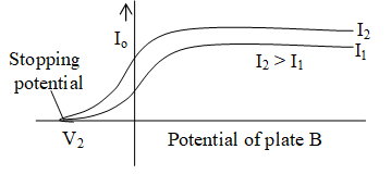
If the intensity of the incident light is increased (from I1 to I2) and frequency is kept same then the variation of the photoelectric current with the potential B is shown in figure. Thus, we find that intensity of incident light does not effect the stopping potential.
Laws of photoelectric emission:
The following are the fundamental laws of photoelectric effect.
i) The photoelectric effect is an instantaneous phenomenon. The time lag between incidence of radiation and emission of photoelectrons is very small.
ii) For a given frequency of incident radiation. The photo electric current is proportional to the intensity of incident radiation.
iii) For a given metal, there exists a certain minimum threshold frequency of incident radiation so that photoelectrons can be ejected from the metal surface. If the frequency is below the threshold frequency no electron can be emitted from the metal surface, no matter whatever may be the intensity of the incident radiation.
iv) The kinetic energy of photo electrons is independent of the intensity of incident radiation but only depends upon its frequency i.e. maximum kinetic energy of the photoelectron is directly proportional to the frequency
v) The photoelectric emission is independent of temperature of the cathode.
vi) The number of electrons emitted per second or the photocurrent is proportional to the intensity of incident light.
vii) The K.E of the emitted electron increases with the increase of frequency of incident radiation. K.E. of the emitted electrons is independent of intensity of incident light.
vii) If the frequency of incident radiation is less than certain critical value, photoelectric emission is not possible. This frequency is known as threshold frequency (ν0). It is different for different metals or emitters. Here the corresponding wavelength is known as threshold wavelength (λ0).
If ν < ν0 or λ > λ0 no photoelectric emission.
If ν = ν0 or λ = λ0 Photoelectrons will just eject with zero K.E.
If ν > ν0 or λ < λ0 Photoelectrons eject with certain K.E.
Planck’s Hypothesis
Electromagnetic radiation carries energy in packets or bundles known as photons or quanta. Max Planck in 1901 put forward the following hypothesis.
a) Energy of an electromagnetic wave is an integral multiple of the product of Planck’s constant (h) and the frequency (ν) of the wave.
i.e. E = nhν where h = 1, 2, 3 ……….
Where n indicates no of photons.
b) A source of EM waves emits energy when it goes from higher to lower energy state and absorbs energy when it goes from lower to higher energy state.
Photon
A photon is a packet or bundle of energy and the energy associated with a photon is given by
E = hν where h =
Properties of Photons
a) Photons have both wave nature and particle nature.
b) Photons are electrically neutral. So they are not deflected by electric and magnetic fields.
c) Photons possess mass only when they are in motion. Momentum of photon is equal to . (rest mass of photon is zero)
d) Effective mass of photon
e) Power of a radiant source is number of photons emitted per second.
f) Intensity of radiation
For a point source , where d is the distance between the source and the target.
g) Energy of photon
Parameters related to Photoelectric Emission
a) The minimum frequency of incident radiation required to release the electron from metal surface is known as threshold frequency (ν0).
b) The maximum wavelength of incident radiation required to release the electron from metal surface is known as threshold wavelength (λ0)
c) The minimum energy of photon required to liberate the electrons from the metal surface is called its work function (). Different metals will have different work functions.
(λ is in angstrom)
i) Work function is the characteristic of the emitter and not of emitted electrons. Its value depends on the impurities present on the emitter surface.
ii) As the atomic number of element increases, the work function decreases.
iii) Work function decreases with the increase of temperature of the metal.
d) The negative potential that must be applied to the anode (or collector) to just stop the electrons reaching the anode from cathode or emitter is called stopping potential or cut-off potential (Vs). Work done by the stopping potential is equal to loss in maximum K.E of the electrons.
i.e.
i) Stopping potential depends on frequency of incident light and the nature of cathode material. It does not depend on the intensity of incident light.
ii) Stopping potential increases with increase in the frequency of the incident radiation. Eg : stopping potential for violet light is greater than for red light.
iii) Stopping potential in volt is numerically equal to maximum K.E of photoelectrons in eV.
iv) Stopping potential is independent of the illumination power of the source and the distance between the source and emitter surface.
Einstein photo electric equation
Einstein’s applied Planck’s quantum theory of light to the photoelectric effect. According to Einstein one electron is emitted from a metal surface if one photon of suitable frequency is incident on the metal. Suppose a photon of suitable frequency is incident on the metal as shown in fig. The energy of the photon is spent in two ways.
i) A part of energy is used by the electron to overcome the surface barrier to come out of the metal surface. This part of energy is equal to work function () of the metal.
ii) The remaining part of the energy is used to give a velocity to the emitted photoelectron. This part of energy is equal to the kinetic energy of the emitted photo electron (i.e. )
According to the law of conservation of energy
……. (i)
If ν = ν0 (threshold frequency), then the free electron is just emitted from the metal surface with zero velocity i.e. .
Hence equation (i) can be written as
.….. (ii)
which is the expression for the work function of the metal substituting the value of in equation (i), we get
..….. (iii)
Which is Einstein’s photoelectric equation. This equation show that
If Vo is stopping potential of collector, then work done (eVo) to stop the electron is equal to the maximum K.E. of electron
….. (iv)
from equation (iii) and (iv)
i.e.
Therefore the slope of the graph drawn between the stopping potential and frequency of incident radiation is .
This explains the experimental result shown in figure.
Various forms of Einstein’s photoelectric equation:
i)
ii)
maximum K.E. of emitted electrons =
iii) Maximum K.E. of emitted electrons = .
iv) If Vo is the value of stopping potential, then
Photoelectric cell
A device which converts light energy into electrical energy is called photoelectric cell or simply photocell. It is also known as an electric eye.
Photoelectric cell works on the principle of photoelectric effect.
There are three types of photoelectric cells
i) Photo emissive cell ii) Photo voltage cell iii) Photo conductive cell
i) Photo emissive cell
This cell is based on the fact that electrons are emitted from a photo sensitive surface when light of suitable frequency falls on it.
It consists of an evacuated glass or quartz bulb containing anode and cathode C. The cathode is semi-cylindrical metal cathode on which a layer of photo-sensitive alkali metal is deposited. The external circuit connected to anode and cathode consists of a high tension battery in series with the high resistance R.
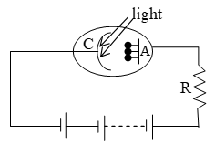
When light is incident on the cathode, it emits photo electrons which are attracted by the anode. The photoelectrons constitute a small current which flows through the external circuit.
The photo electric current can be increased by filling some inert gas like Argon into the bulb. The photo electrons emitted by cathode ionize the gas by collision and hence the current is increased. The +ve ions move towards the cathode while –ve ions and electrons move towards the anode.
ii) Photo conductive cell
It is based on the principle that conductivity of a semiconductor increases with increase in the intensity of incident light.
A metal layer (say iron) has thin layer of semi conductor (selenium) accompanied with a thin film of some special material as shown in figure. When suitable light falls on thin film resistance of selenium decreases allowing a flow of current in the circuit.
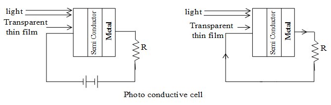
iii) Photovoltaic cell
It works on the principle that photoelectric emission can develop potential difference between suitable substances.
It consists of a metal layer (Au, Ag or Cu) and a layer of semiconductor accompanied by a thin transparent film of some special material as shown in figure. When light falls on the transparent film, photoelectrons are emitted by the semiconductor layer which are captured by thin film. This causes a P.D. across the layers and hence current flows in the circuit. It is clear that the photo cell itself work as a source of electric current in the presence of light.
Applications of photoelectric cell
Photoelectric cells are being used in varied fields of industry and research. Some of these applications are given below.
i) Photoelectric cells are used for the reproduction of sound recorder on one edge of the cinema films.
ii) Photoelectric cells are used for switching on or off the street light automatically.
iii) Photoelectric cells are used in burglar alarm and fire alarm.
iv) Photoelectric cells are used in television camera.
v) Photoelectric cells are used for counting operations
vi) Photoelectric cells are used in industry to locate flaws in metal sheets.
vii) Photoelectric cells are used in cameras for the automatic adjustment of aperature. viii) Photoelectric cells are used to measure the temperature of the stars.
ix) Photoelectric cells are used to control the temperature.
x) Photoelectric cells are used to control the temperature of chemical reaction
xi) Photoelectric cells are used to determine plank’s constant.
3. X RAYS, MOSELEY’S LAW AND COMPTON EFFECT
X Rays
When highly energetic electrons are made to strike a metal target, electromagnetic radiation comes out. A large part of this radiation has wavelength of the order of 0.1 nm and is known as X-rays. X-ray was discovered by German scientist Roentgen in 1895 while investigating discharge of electricity through rarefied gases. He observed fluorescence on a screen coated with Barium cyanide due to some invisible radiation called X-ray from discharge tube.
Nature of X-Rays
i) X-rays are electromagnetic waves. Wavelength of X-rays lie in between the ultraviolet rays and -rays.
ii) Wavelength of X-rays is of the order of 1Ao where as their wavelength range is from 0.1A to 100A. Frequency range is . Energy range is from 100 eV to 10,000 eV.
iii) The intensity of X-rays depend on the number of electrons striking the target or filament current. By increasing the filament current, intensity of the X-rays can be increased.
iv) The frequency of X-rays depends on the accelerating potential or kinetic energy of electrons striking the target.
i.e. or and or X-rays of very low wavelength are called hard X-rays and X-rays of larger wavelength are called soft X-rays.
X-Rays Spectrum
Experimental studies by Bragg and Mosley, revealed that there are two types of X-rays spectra namely.
a) Continuous X-ray spectrum b) Characteristic X-ray spectrum.
a) Continuous X-ray spectrum
It is formed due to scattering of high speed electrons that strike the target. When high energy electrons move close to the nucleus of target atom then these get decelerated and x-rays of continuous frequency are emitted. The electron rarely loses whole of its energy in a single collision. Generally it undergoes a sequence of collisions with atoms at the target before coming to rest, thus emitting photons of smaller frequency or longer wave length.
Continuous X-rays are due to the conversion of kinetic energy of electrons into X-ray photon. If the applied voltage is V. Then work done in accelerating electron is equal to its kinetic energy E.
………. (i)
where e, m and V stand for charge, mass and voltage of electron and V is its velocity. If this K.E. is totally converted into photon of energy E. then
E = ………. (ii)
From equation (i) and (ii)
Therefore, continuous X-rays have a cut off wavelength (λmin) for a given potential applied. Thus, the minimum wavelength of X-rays generated in cooling tube is inversely proportional to the accelerating voltage. This is known as Duan and Haunt’s law.
In this, the wavelengths are continuous and are independent of the nature of material of target and wavelengths are dependent only on the potential applied.
b) Characteristics of X-ray spectrum
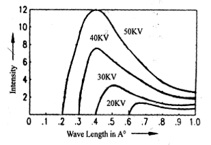
Characteristic X-rays are produced by the atoms of the target element when the electrons in their innermost shell are removed and the remaining electrons in the atoms rearrange themselves. The wavelengths of these X-rays depend upon the target material. The intensity wavelength graph show sharp peaks at certain wavelengths called characteristic wavelengths of the element superimposed over the continuous X-ray spectrum.
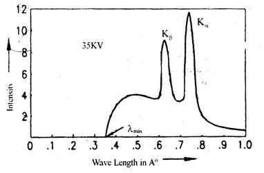
Figure shows the characteristic spectrum produced when 35 KV potential is applied to Coolidge tube and the high energetic electrons hit a Molybdenum target. We see a broad, continuous spectrum of X-radiation on which two peaks of sharply defined wavelengths are superimposed. The sharp peaks are labeled as K and K.
When the high energetic electrons strike a surface of the target, they penetrate into the atoms and knock out the tightly bound electrons from the innermost shells. (K and L shells) of the atoms. If an electron from K-shell is knocked out, then an electron in one of the shells with higher energy jumps to K-shell to fill the vacancy. When such a transition takes place, the difference of energy ΔE is converted into an X-ray photon of wavelength
.
As energies of the orbits are constants for a given target material, when an electron from L shell jumps to fill the vacancy created in K-shell, the difference of energies of the shells , the X-ray photon with characteristic wavelength λ is produced. The transitions from L shell to K shell produce Kα X-ray peaks or simply Kβ spectral line.
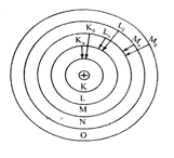
Similarly transition from M shell to K shell produces Kβ spectral line. These are called K-series of spectral lines.
Similarly we get L-series of spectral lines due to transition of electrons from M and N shells to L-shell. M series of spectral lines obtained due to transition of electron from O and N shells to M-shells.
Mosley’s Law
Mosley examined the characteristics X-ray spectra of different element in 1913. He observed that if the square root of the frequency ν of the most intense spectral line (says Kα) is plotted against atomic number Z of the target, then we get a straight line graph. It is clear from the graph that
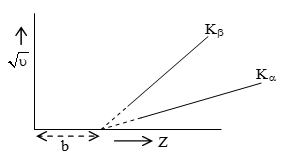
or
Here a is constant of proportionality and b is screening constant. The value of a and b depending upon the spectral line. For K series, b = 1 and for L series b = 7.4
i.e.
the value of a for Kα line is Rc, where R is the Rydberg constant and c is the speed of radiation of light. Equation (i) is the mathematical statement of Moseley’s law i.e. the frequency of characteristic X-ray spectral line is directly proportional to the square of atomic number of target element.
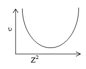
Note:
(i) The graph between Z2 and will be as shown.
(ii) Wavelength of Kα line is given by
iii) X-rays spectra are absent in the solar spectrum.
iv) X-rays are very penetrating indeed. But as these pass through some thickness of material, their intensity is decreased. Thus, the material has partly absorbed the X-rays. The intensity gradient of X-rays is directly proportional to the intensity of X-rays at that point
i.e.
……….. (i)
where μ is the absorption coefficient of the material
again
Integrating both sides we get
v) Absorption coefficient (μ): Its value depends upon the wavelength λ of x-rays and atomic number Z of the material. It is given by
where C is constant and ρ is the density of the absorbing material.
Compton Effect
According to Compton, when monochromatic X-rays fall on electrons, the scattered X-rays contain two components one having longer wavelength and the other having same wavelength as that of the incident X-rays.
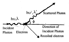
The X-rays photon having longer wave length is known as modified radiation or in coherent scattering. This phenomenon of change in wavelength of the scattered X-rays photon is known as Compton effect. Compton assumed that the collision between X-rays photon and electron is perfectly elastic. So energy and linear momentum of the system remain conserved. The change in the wavelength of X-rays photon is called Compton shift and is given by
Compton shift
where mo = rest mass of electron, = angle of scattering.
λ = wavelength of incident radiation
λ’ = wavelength of scattering radiation
Special cases
i) If = 0o, Δλ = 0 no scattering along the direction of incidence (un modified)
ii) If = 90o or 270o,
iii) If = 180o,
i.e. maximum Compton shift is equal to the twice of the Compton wavelength
Note:
i) In Compton scattering an electron is also ejected with an energy dependent on its direction. It is known as Compton effect.
ii) Compton shift depends on the scattering angle and rest mass of the particle which scatters the photon.
iii) Direction of recoil of electron is given by
4. DUAL NATURE OF MATTER AND HEISENBERG’S UNCERTAINTY PRINCIPLE
Dual nature of particles or matter
Wave theory of electromagnetic radiation explained the phenomenon of interference, diffraction and polarization. On the other hand, quantum theory of electromagnetic radiation successfully explained the photoelectric effect, Compton effect, black body radiation, X-ray spectra etc. Thus radiation have dual nature i.e. wave and particle or quantum nature. A French physicist Louis de Broglie suggested that the particles like electrons, protons, neutrons etc have also dual nature. His suggestion was based on the assumptions that
i) The universe is made of particles and radiation and both these entities must be symmetrical.
ii) The nature loves symmetry.
de Broglie’s hypothesis
According to de Broglie, every moving particle is associated with a wave which controls the particle in every aspect. The wave associated with a particle is called matter wave or de Broglie wave. de Broglie proposed that the wavelength of material particle would be related to its momentum in the same way as for a photon (i.e. p = ) that is for a particle of mass moving with speed v, Broglie wavelength is given by
where h = Planck’s constant
The de Broglie waves though often referred to as matter waves are not composed of matter. The intensity of wave at a point represents the probability of the associated particle being there.
Derivation of de Broglie wavelength
According to plank’s quantum theory, the energy of a photon of radiation of frequency f and wavelength λ is given by
E = hν ……… (i)
where h = plank’s constant.
If photon is considered a particle of mass m then according to Einstein’s energy, mass relation, the energy E of the photon is
E = mc2 where c = velocity of light.
Since the energy of the photon in the two cases is the same
∴ hν = mc2 …….. (ii)
or
the quantity mc is the momentum P of the photon having mass m and traveling with velocity c.
…….. (iii)
de Broglie proposed that equation (iii) is completely a general formula and is applicable to photon as well as other moving particles. Thus if a particle has mass m and moves with a velocity v, its momentum is mv. The wavelength of the wave associated with this moving particle is given by
This is de Broglie wave equation for a material particle.
Note that m is the relativistic mass of the particle. The velocity of the particle is comparable to the velocity of light, then mass of the particle is given by
Some facts: The following points may be noted about matter waves or pilot waves
i)
ii) The greater the momentum of the particle, the shorter is the wavelength
De Broglie wavelength of an electron
Suppose an electron at rest has been accelerated through a potential difference at V volts and gains a velocity v. If m and e are mass and charge of electron respectively, then
Work done on electron = eV
K.E. gained by electron =
or velocity of electron
or
substituting the value of h, e and m we get
Note:
(i) For a gas molecule of mass m at temperature T Kelvin, the de Broglie wavelength is given by
ii) Velocity of the matter wave is not constant since it depends upon the velocity of the material particle.
iii) These waves travel faster as compared to EMW.
iv) de Broglie wavelength is also given by
Heisenberg’s Uncertainty Principle
It states that it is not possible to determine precisely both the position and the momentum or velocity of moving microscopic particle simultaneously.
Mathematically,
or
Where, Δx, Δp and Δv are uncertainties with respect to position, momentum and velocity respectively and h = Planck’s constant. (6.626 x 10⁻³⁴ Js or kg m2s-1)
This inability is not due to lack of proper instruments but due to the limitations imposed by nature on such measurements.
Thus Heisenberg’s uncertainty principle is one of the basic principles of wave mechanics.
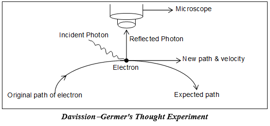
Physical concept of uncertainty principle
To determine the position of an object we must be able to ‘see’ the object. This can be done with help of light of suitable wavelength.
When a beam of light falls on an object, the photon of this incident light strikes the electron and the reflected light photon is seen in microscope.
Case-I: If the object is large, its position and velocity will not change by the impact of striking photons. Thus it will be possible to determine both the position and velocity of the object simultaneously.
Case-II: If the target object is a microscopic body i.e. electron, the position as well as the momentum (or velocity) of the electron are disturbed.
According to principle of optics, the accuracy in measurement depends upon the wavelength of light. The uncertainty in position =
Hence, shorter the λ, greater the accuracy, higher the frequency, higher the energy
Hence, this high energy photon on striking the electron changes its speed as well as direction (i.e. position)
In other words, shorter λ higher momentum (p), greater uncertainty in v
larger λ lower momentum (p), greater uncertainty in Δx
Thus, uncertainty principle is valid for all conjugate pair of physical quantities, for example position and momentum, energy and time and so on.
Significance of Heisenberg’s uncertainty principle
Like de Broglie equation, it has more significance for microscopic particles (i.e electrons).
Reason: The energy of photon is not sufficient to charge the position and velocity of larger bodies when it collides with them. e.g. the light from a torch falling on a running cat in a dark room neither changes the speed of the cat nor its position (i.e. direction).
This principle is more significant for the microscopic particles because the product of the Δx and Δv is quite measurable i.e.
i) For an electron (measurable)
Here, if uncertainty in Δx is 10-4 m then uncertainty in Δv is 1.0 ms-1 (measurable – more significantly)
ii) For a particle of 10-6 kg;
(no significance ∴ not measurable)
Therefore, for a particle of mass greater than 1 mg (or 10-6 kg) the product of Δx and Δp will be still smaller, hence, these values are ignored (Not measurable).
Since, in everyday life, we come across large objects only, the position and velocity of which can be measured accurately. Hence, Heisenberg’s uncertainty principle has no significance in everyday life. In other words, uncertainty principle has the fundamental limitation of nature.

SOLVED EXAMPLES
Example 1 The volt age across the electrodes of a cathode gun is 500V. Calculate (i) The energy gained by the electron (ii) The speed of the electron (iii) The momentum of the electron.
Solution:
Here V = 500 V, m = ,
i) Energy gained by electron = eV =
ii) If v is velocity of the electron, then
iii) Momentum of electron = mv
Example 2
In Thomson’s setup for determining e/m, the kgm/s same high tension d.c. supply provides potential to the anode of the acceleration column as also to the +ve deflecting plate in the region of cross fields. If the supply voltage is doubled, by what factor should the magnetic filed be increased to keep the electron beam undeflected?
Solution
In Thomson method, the value of e/m is given by
We know (d = distance between the plates)
since e, m and d are constant
also
Example 3
Calculate the radius of a drop of oil, density 900 kg/m3 which falls with a terminal velocity of m/s through air of viscosity . Ignore the density of air. If the charge on the drop is 3e, what potential difference must be applied between two plates 5 mm apart to keep the drop stationary?
Solution
Given that
We know the radius of the drop
Since the drop is stationary, the force on the drop due to electric field is equal to the weight of the drop.
∴ qE =mg
Now V = E.d =
Example 4
In Millikan’s oil drop experiment, a charged oil drop of mass density 880 kg/m is held stationary between two parallel plates 6.0 mm apart held at potential difference of 103V. When the electric field is switched off, the drop is observed to fall a distance of 2.0 mm in 35.7 second.
i) What is the radius of the drop?
ii) Estimate the charge on the drop. How many excess electrons does it carry? (The upper plate in the experiment is at higher potential).
Viscosity of air = , Density of air = .
Solution
Given that
Distance travelled by oil drop in 35.7 sec = 2.0 mm =
ii)
for the drop to be stationary, the force on the drop due to electric field must be equal and opposite to the effective weight of drop i.e.
=
Now q = ne
Example 5
Ultraviolet light of wavelength 3600 is made to fall on a smooth surface of potassium. Determine (i) Threshold wavelength (ii) Maximum energy of emitted photoelectrons (iii) Stopping potential (iv) Velocity of the most energetic photoelectron (v) Momentum of photon. Given that work function for potassium is 2eV.
Solution
Given that
i) work function
ii) Maximum K.E. of emitted photoelectron
iii) If Vo is the stopping potential in volt, then
eVo = maximum kinetic energy
iv) Let Vmax be the maximum velocity of emitted photoelectrons
v) Momentum of a photon,
Example 6
Find the number of photons emitted per second by a 25W source of monochromatic light of wavelength 6000Ao.
Solution
Given that λ = 6000Ao
Power of source = 25W= 25 J/s
Energy of one photon = hν =
∴ Number of photons emitted/second =
Example 7
Calculate de Broglie wavelength of 500 eV proton. Given that mass of proton = .
Solution
Given that
de Broglie wavelength of proton is given by
Example 8
X-rays of wavelength fall on a metal plate. Find the wavelength associated with photoelectron emitted. Neglect work function of the metal. Given .
Solution
Given that λ = 0.82 , h = , C = , = 0.
Maximum kinetic energy of electron,
de Broglie wavelength associated with photo electron
Example 9
A photon is accelerated to a velocity of 3⨯107 ms-1. If the velocity can be measured with a precision of 0.5%, calculate the uncertainty in position of photon
(h=6.6×10⁻³⁴ JS, mass of photon = 1.66×10⁻²⁷ kg)
Solution
According to Heisenberg’s principle
Illustration 10
A Golf ball has a mass of 40 gm and a speed of 45 m/s. If the speed can be measured within accuracy of 2%, calculate the certainty in position.
Solution
Uncertainty in speed
From uncertainty principle,