


1. INTRODUCTION
When a resistor is connected across the terminals of a battery, a current is established in the circuit. The current has a unique direction, it goes from the positive terminal to the negative terminal via the external resistor. The magnitude of the current also remains almost constant. This is called direct current (dc).
If the direction of the current in a resistor or in any other element changes alternately, the current is called an alternating current (ac). In this chapter, we shall study the alternating current that varies sinusoidally with time.
2. ALTERNATING CURRENT(A.C.)
• Electric current, which keeps on changing in magnitude and direction periodically is defined as alternating current.
• It obeys Ohm’s law and Joule’s heating law.
It is produced using the principle of electromagnetic induction.
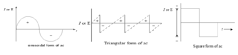
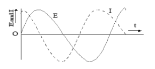
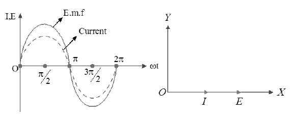
• Graphical representations for alternating quantities can be represented in the form of the following graphs.
3. ALTERNATING VOLTAGE (A.V)
• The voltage, which changes in magnitude and direction with respect to time is defined as alternating voltage.
• The alternating voltage in general use is sinusoidal voltage. It is produced by rotating a coil in a uniform magnetic field with uniform angular velocity.
4. ADVANTAGES OF ALTERNATING CURRENT OVER DIRECT CURRENT
• The cost of generation of ac is less than that of dc.
• ac can be conveniently converted into dc with the help of rectifiers.
• By supplying ac at high voltages, we can minimise transmission losses or line losses.
• ac is available in a wide range of voltages. These volatages can be easily stepped up or stepped down with the help of transformers.
5. DISADVANTAGES OF ALTERNATING CURRENT OVER DIRECT CURRENT
• ac is more dangerous than dc.
• ac is transmitted more by the surface of the conductor. This is called skin effect. Due to this reason that several strands of thin insulated wire, instead of a single thick wire, need be used.
• For electrorefining, electro – typing electroplating, only dc can be used but not ac.
6. INSTANTANEOUS VALUE OF CURRENT OR VOLTAGE (I or E)
• The value of current or voltage in an ac circuit at any instant of time is called its instantaneous value.
• Instantaneous current,
• Instantaneous voltage,
Where is called phase
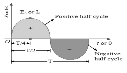
7. AMPLITUDE OF A.C. ( PEAK VALUE) () or ( )
It is the maximum value of A.C. The value of A.C. becomes maximum twice in one cycle.
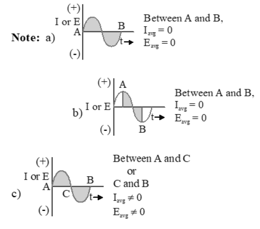
Note: Average value of a function F (t) over a period of T is given by
8. AVERAGE VALUE OF A.C. < I >
• The value of current at any instant ‘t’ is given by
• The average value of a sinusoidal wave over one complete cycle is given by
For half cycle:
• Similarly
9. FREQUENCY OF A.C. (f)
• It is the number of cycles completed by A.C. in one second.
10. TIME PERIOD OF A.C. (T)
• It is the time taken by A.C. to complete one cycle.
f = 1/ T
11. MEAN SQUARE VALUE OF A.C. <>
12. R.M.S. VALUE () or EFFECTIVE VALUE (I) or VIRTUAL VALUE OF A.C.
It is the square root of the average of squares of all the instantaneous values of current over one complete cycle.
• It is equal to that direct current which produces same heating in a resistance as is produced by the A.C. in same resistance during same time.
13. MEAN SQUARE VALUE OF A.C. <>
14. FORM FACTOR
Form factor =
Form factor =
We know that
Form factor =
Note :
• ac ammeter and voltmeter read the r.m.s value i.e., effective value of alternating current and voltage respectively.
• ac can be measured by using hot wire ammeters or hot wire voltmeters because the heat generated is independent of the direction of current.
• ac produces the same heating effects as that of dc of magnitude i =
• ac is more dangerous than dc of same voltage.
100V ac means
100V dc is equivalent to
• ac can be produced by the principle of electromagnetic induction.
15. POWER IN ac CIRCUITS
In dc circuits power is given by P = VI. But in ac circuits, since there is some phase angle between voltage and current, therefore power is defined as the product of voltage and that component of the current which is in phase with the voltage.
Thus P = EI cos , where E and I are r.m.s. values of voltage and current.
Power factor: The quantity cos is called power factor.
a) In stantaneous power : Suppose in a circuit then
b) Average power (True power) : The average of instantaneous power in an ac circuit over a full cycle is called average power. Its unit is watt i.e.
Average power over complete cycle,
c) Apparent or virtual power : The product of apparent voltage and apparent current in an electric circuit is called apparent power. This is always positive.
16. RESISTANCE (R) It is the opposition offered by a conductor to the flow of direct current.
17. IMPEDANCE (Z) It is the opposition offered by a conductor to the flow of alternating current.
18. ADMITTANCE(Y): Reciprocal of impedance of a circuit is called admittance of the circuit.
admittance (Y) =
S.I. Unit:ohm-1 i.e. mho or siemen.
19. PHASE: The physical quantity which represents both the instantaneous value and direction of A.C. at any instant is called its phase.
• It is dimensionless quantity and its unit is Radian
• Phase Difference: The diffrerence between the phases of current and voltage is called Phase difference.
• If alternating emf and current are then phase difference is
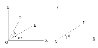
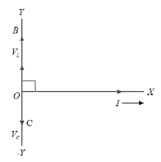
• The quantity varies sinusoidally with time and can be represented as projection of a rotating vector, is called as phasor.
• A diagram, representing alternating emf and current (of same frequency) as rotating vectors (Phasors) with phase angle between them is called as phasor diagram.
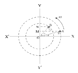
• In the above figure , and represent two rotating vectors having magnitudes and in anti clock wise direction with same angular velocity ‘ ’.
• OM and ON are the projections of and on Y-axis respectively.
• OM = E and ON = I, represent the instantaneous values of alternating emf and current.
• represents the phase angle by which current leads the alternating emf .
• The phasor diagram, in a simple representation is
Note:If e.m.f (or voltage) in A.C. is E = sint and the current I = sin (ωt+φ) Where phase difference φ is Positive if current leads,Negative if current lags and zero if current is inphase with the emf (or voltage).
instantaneous emf is
instantaneous current
where ; Current leads emf by
Current lags emf by or emf leads current by
20. A.C THROUGH A RESISTOR
• A pure resistor of resistance R is connected across an alternating source of emf
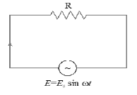
• The instantaneous value of alternating emf is
• The instantaneous value of alternating current is
• Peak value of current,
• Phasor diagrams:
• emf and current will be in phase
• emf and current have same frequency
• Peak emf is more than peak current
• The value of impedance (Z) is equal to R and reactance (X) is zero
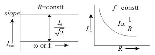
• Apart from instantaneous value, current in the circuit is independent of frequency and decreases with increase in R (similar to that in dc circuits).
21. POWER
• power factor
• Instantaneous power
• Average power over time ‘T ‘ sec =
22. A.C THROUGH AN INDUCTOR
• A pure inductor of inductance L is connected across an alternating source of emf E
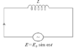
• The instantaneous value of alternating emf is ……(1)
• The induced emf across the inductor = which opposes the growth of current in the circuit. As there is no potential drop across the circuit, so
On integrating
…..(2)
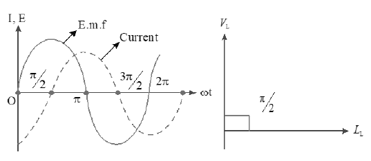
• The instantaneous value of alternating current is
Where Peak value of current,
• From equation 1 & 2
Phase difference between alternating voltage and current is
• The alternating current lags behind the emf by a phase angle of
• Phasor diagram
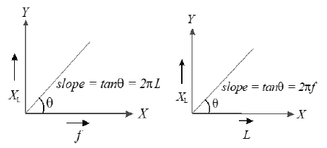
23. INDUCTIVE REACTANCE ()
• The opposition offered by an inductor to the flow of ac is called an inductive reactance.
• The quantity L is analogous to resistance and is called reactance of Inductor represented by L X .
• It allows D.C. but offers finite impedance to the flow of A.C.
• Its value depends on L and f.
• Inductance not only causes the current to lag behind emf but it also limits the magnitude of current in the circuit.
• ,
• For dc,
For ac, high frequencies,
dc can flow easily through inductor.
• Inductive reactance in terms of RMS value is
Power supplied to inductor
• The instantaneous power supplied to the inductor is
So, the average power over a complete cycle is
Since the average of sin over a complete cycle is zero.
Thus, the average power supplied to an inductor over one complete cycle is zero.
24. A.C THROUGH A CAPACITOR
• When an alternating emf is applied to a capacitor, then alternating current is constituted in the circuit. Due to this, charge on the plates and electric field between the plates of capacitor vary sinusoidally with time.
• At any instant the potential difference between the plates of a capacitor is equal to applied emf at that time.
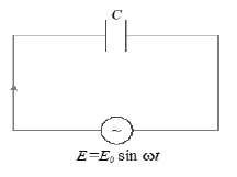
• A capacitor of capacity C is connected across an alternating source of emf
• The instantaneous value of alternating emf is
• Let q be the charge on the capacitor at any instant.
Accoding to kirchhoff’s loop rule
…….(2)
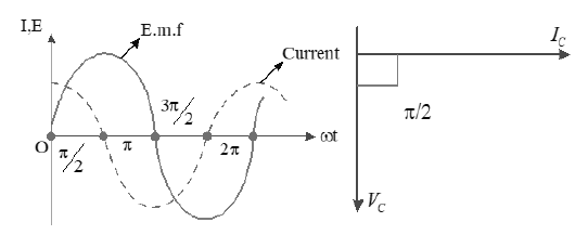
• The instantaneous value of alternating current is
…….(2)
where peak value of current,
• From equation 1 & 2
current leads the emf by an angle .
25. PHASOR DIAGRAM
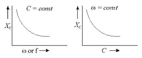
26. CAPACITIVE REACTANCE ()
• The resistance offered by a capacitor to the flow of ac is called capacitive reactence.
• The quantity is analogous to resistance and is called reactance of capacitor represented by
• It is the part of impedance in which A.C. leads the A.V. by a phase angle of .
• Its value is .
• Its value depends on C and f.
• It bypasses A.C. but blocks D.C.
• It is produced due to pure capacitor or induced charge.
•
Note: Resistance, Impedance and Reactance have the same units and Dimensional Formulae.
i.e. SI unit is ohm; Dimensional Formula is
Power supplied to capacitor:
• The instantaneous power supplied to the capacitor is
So, the average power over a complete cycle is zero
since over a complete cycle.
no power is consumed in a purely capacitive circuit.
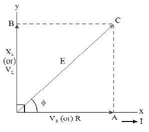
28. A.C THROUGH LR SERIES CIRCUIT
• LR circuit consists of a resistor of resistance R and an inductor of inductance L in series with a source of alternating emf
• The instantaneous value of alternating emf is
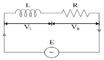
• The potential difference across the inductor is given by, ……(1)
• The potential difference across the resistor, ……(2)
current I lags the Voltage by an angle of ,
Therefore, the resultant of is
Using equations ( 1 ) and (2), we get
where is the inductive reactance.
or ……..(3)
The effective opposition offered by LR circuit to ac is called the impedance of LR circuit.
Let be the angle made by the resultant of and with the X-axis, then from figure, we get
or
Note: In series LR circuit, emf leads the current or the current is said to lag behind the emf by an angle
Current in L-R series circuit is given by
(or)
Note:
•
Thus increases with the frequency of ac, so is low for lower freqeuncy of ac and high for higher frequency of ac
• The phase angle between voltage and current increases with the increase in the frequency of ac
29. C-R SERIES CIRCUIT WITH ALTERNATING VOLTAGE
• Let an alternating source of emf is connected to a series combination of a pure capacitor of capacitance (C) and a resistor of resistance (R) as shown in figure (a)
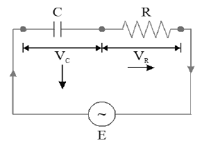
• Let I be the r.m.s value of cu rrent flowing through the circuit. The potential difference across the capacitor,
…… (i)
• The current leads emf by an angle when ac flows through capacitor.
• The potential difference across the resistor,
……. (2)
• The emf and current are in phase when ac flows through resistor.
Phasor diagram.
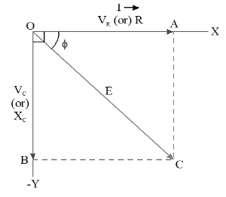
• In figure is represented by OB along negative
Y – axis and the current I is represented along X – axis.
• is represented by OA along X – axis.
• The resultant potential difference of is represented by OC.
• Also, the emf and current are in phase when ac flows through the resistor. So, is represented by OA along X-axis.
• Therefore, the resultant potential difference of is represented by OC and is given by
Using equations (i) and (ii), we get
or
From the above equations of I and E, we have
Where is the effective opposition offered by the CR circuit to ac, which is the impedance of CR circuit.
Let be the angle made by E with X-axis
or
In series CR circuit, emf lags behind the current or in other words, the current is said to lead the emf by an angle given by the above equation.
Current in C-R series circuit is given by
(or)
Note:
• The resultant potential difference of is represented by OC Impedance of CR circuit.
Thus
• The resultant potential difference of is represented by OC For very high frequency (f) of ac. Z R and for very low frequency of ac
• Phase angle between voltage and current is given by
As f increases, phase angle decreases.
30. L – C SERIES CIRCUIT WITH ALTERNATING VOLTAGE
• Let an alternating source of emf 0 is connected to the series combination of a pure capacitor of capacitance (C) and an inductor of inductance (L) is shown in fig.

• Let I be the rms value of current flowing in the circut
• The P.D across ‘L’ is
• The current I lags by an angle .
• The P.D across capacitance is .
• The current I leads by an angle .
• The voltage are represented by OB and OC respecitvely.
The resultant P.D of is
• From the above equations, Impedance of L -C circuit is
• If potential difference
• Now current lags behind voltage by .
• If resultant potential difference
Now current leads emf by .
If
Current
In L – C, circuit, the phase difference between voltage and current is always .
Power factor .
So, power consumed in L – C circuit is
In L – C circuit no power is consumed.
Note:
• In L – C, circuit, the impendence
Current .
So, the impedence and current varies with frequency.
• At a particular angular frequency,
and current becomes maximum and resonance occurs.
At resonance Z = 0 and .
Resonant angular frequency
Resonant frequecny .
31. A.C THROUGH LCR SERIES CIRCUIT
• A circuit containing pure inductor of inductance (L), pure capacitor of capacitance (C) and resistor of resistance (R), all joined in series, is shown in figure.
• Let E be the r.m.s value of the applied alternating emf to the LCR circuit.
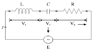
• The potential difference across L,
……(i)
• The potential difference across C,
……(ii)
• The potential difference across R,
……(iii)
PHASOR DIAGRAM
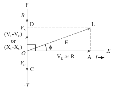
• Since VL and VC are in opposite phase, so their resultant (VL –VC) is represented by OD (Here VL > VC)
• The resultant of VR and (VL–VC) is given by OL.
The magnitude of OL is given by
Impedance (Z) of LCR circuit is given by
• Let be the phase angle between E and I, then from Phasor diagram
Current in L-C- R series circuit is given by
(or)
• If XL and XC are equal then Z = R i.e., expression for pure resistance circuit.
If XL = 0 then i.e., expression for series RC circuit.
• Similarly if XC = 0 then i.e. expression for series RL circuit.
Also,
Case (i) : If XL > XC then is +ve. In this case the current lags behind the emf by a phase angle
Case (ii) : If XL < XC then is -ve. In this case the current leads the emf by a phase angle
Case (iii): If XL = XC then is 0. In this case the current and emf are in phase.
• If XL > XC, then the circuit will be inductive.
• If XL < XC, then the circuit will be capacitive.
• If XL = XC, then the circuit will be purely resistive.
• The LCR circuit can be inductive or capacitive or purely resistive depending on the value of frequency of alternating source of emf.
• At some frequency of alternating source, XL > XC and for some other frequency, XL < XC. There exists a particular value of frequency where XL = XC (This situation is
explained under resonance of LCR series circuit )
Note: Relation between applied pd & pd’s across the components in L – C – R circuit
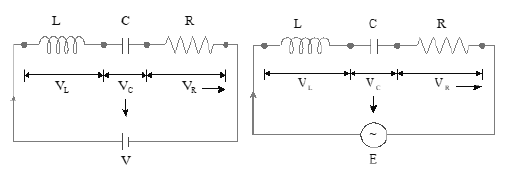
For ‘dc’ For ‘ac’
V = IZ
(only before steady state)
where
Note: Rules to be followed for various combinations of ac circuits
• Compute effective resistance of the circuit as R
• Calculate the net reactance of the circuit as where .
• Resistance offered by all the circuited elements to the flow of ac is impedance ( Z )
• Calculate the peak value of current as
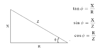
• The phase difference between emf & current can be known by constructing an ac triangle as
32. RESONANT FREQUENCY
Electrical Resonance Series L-C-R Circuit
Electrical resonance is said to take place in a series LCR circuit, when the circuit allows maximum c u r r e n t for a given frequency of alternating supply, at which capacitive reactance becomes equal to the inductive reactance.
The current (I) in a series LCR circuit is given by
………(i)
From the above equation (i), it is clear that current I will be maximum if the impedance (Z) of the circuit is minimum.
At low frequencies, is very small and is very large.
At high frequencies, L is very large and is very small.
For a particular frequency and the impedance (Z) of LCR circuit is minimum and is given by Z = R.
Therefore, at the particular frequency (), the current in LCR circuit becomes maximum. The frequency () is known as the resonant frequency and the phenomenon is called electrical resonance.
Again, for electrical resonance .
i.e. XL = XC
or
or
or ……. (ii)
This is the value of resonant frequency.
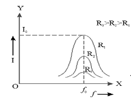
The resonant frequency is independent of the resistanace R in the circuit. However, the sharpness of resonance decreases with the increase in R.
Series LCR circuit is more selective when resistance of this circuit is small.
Note: Series LCR circuit at resonance admit maximum current at particular frequencies, so they can be used to tune the desired frequency or filter unwanted frequencies. They are used in transmitters and receivers of radio, television and telephone carrier equipment etc.
33. RESONANCE IN L – C CIRCUIT
At resonance ,
a) Net reactance X = 0
b)
c) Impedance Z = 0
d) peak value of current
e) Resonant frequency
f) Voltage and current differ in phase by
g) Power factor
34. RESONANCE IN L – C – R CIRCUIT
At resonance,
a) Net reactance X = 0
b)
c) Impedance Z = R ( minimum )
d) peak value of current ( maximum but not infinity )
e) Resonant frequency
f) Voltage and current will be in phase
g) power factor
h) Resonant frequency is independent of value of R.
i) A series L – C – R circuit behaves like a pure resistive circuit at resonance.
35. HALF POWER FREQUENCIES AND BAND WIDTH.
• The frequencies at which the power in the circuit is half of the maximum power (The power at resonance) are called half power frequencies.
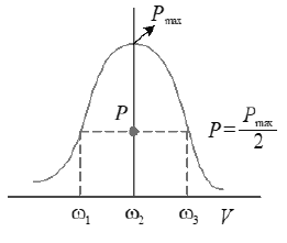
• The current in the circuit at half power frequecies (HPF) is or 0.707 or 70.7% of maximum current (current at resonance).
• There are two half power frequencies
called lower half power frequency. At this frequency the circuit is capacitive.
called upper half power frequency. It is greater than . At this frequency the circuit is inducitve.
• Band width : The difference of half power frequencies is called band width and .
• For series resonant circuit it can be proved
36. QUALITY FACTOR (Q – FACTOR) OF SERIES RESONANT CIRCUIT.
• The characteristic of a series resonant circuit is determined by the quality factor (Q- factor) of the circuit.
• It defines sharpness of i – v curve at resonance when Q – factor is large, the sharpness of resonance curve is more and vice – versa.
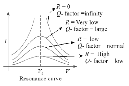
• Q – factor also defined as follows
37. WATTLESS CURRENT:
In an ac circuit, , i.e.., in resistanceless circuit the power consumed is zero, Such a circuit is called the wattless circuit and the current flowing is called the wattless current.
Or
The component of current which does not contribute to the average power dissipation is called wattless current.
wattless current =
38. CHOKE COIL:
• Choke coil (or ballast) is a device having high inductance and negligible resistance.
• It is used to control current in ac circuits and is used in fluorescent tubes.
• The power loss in a circuit containing choke coil is least.
• In a dc circuit current is reduced by means of a rheostat.This resutls in a loss of electrical energy .
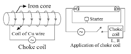
• It consists of a copper coil wound over a soft iron laminated core. This coil is put in series with the circuit in which current is to be reduced.
• Soft iron is used to improve inductance (L) of the circuit.
• The inductive reactance or effective opposition of the choke coil is given by
• For an ideal choke coil r = 0 , no electric cnergy is wasted, i.e., average power P = 0.
• In actual practice choke coil is equivalent to a R – L circuit.
• Choke coil for different frequencies are made by using different substances in their core.
• For low frequency L should be large thus iron core choke coil is used. For high frequency ac circuit, L Should be small, so air cored choke coil is used.
• The choke coil can be used only in ac circuits not in dc circuits, because for dc frequency v = 0. Hence .
• Choke coil is based on the principle of wattless current.
• The current in the circuit with
.
• The power loss in the choke
as
39. LC OSCILLATIONS
A capacitor (C) and an inductor (L) are connected as shown in the figure. Initially the charge on the capacitor is Q
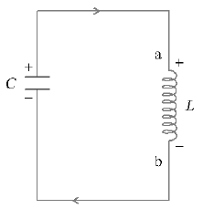
Energy stored in the capacitor The energy stored in the inductor, .
The capacitor now begins to discharge through the inductor and current begins to flow in the circuit. As the charge on the capacitor decreases, decreases but the energy in the magnetic field of the inductor increases. Energy is thus transferred from capacitor to inductor. When the whole of the charge on the capacitor disappears, the total energy stored in the electric field in the capacitor gets converted into magnetic field energy in the inductor. At this stage, there is maximum current in the inductor.
Energy now flows from inductor to the capacitor except that the capacitor is charged oppositely. This process of energy transfer continues at a definite frequency (v). Energy is continuosly shuttled back and forth between the electric field in the capacitor and the magnetic field in the inductor.
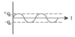
If no resistance is present in the LC circuit, the LC oscillation will continue infinitely as shown.
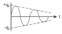
However in an actual LC circuit, some resistance is always present due to which energy is dissipated in the form of heat. So LC oscillation will not continue infinitely with same amplitude as shown.
Let q be the charge on the capacitor at any time t and be the rate of change of current. Since no battery is connected in the circuit,
from the above equations, we get
The above equation is analogus to (differential equation of S.H.M)
Hence on comparing
The charge therefore oscillates with a frequency
and varies sinusoidally with time.
COMPARISON OF L – C OSCILLATIONS WITH SHM : The L – C oscillations can be compared to S.H.M of a block attached to a spring
* In L – C oscillations
* In Mechanical oscillations where K is the spring constant
* In L – C oscilations tells us the potential difference required to store a unit charge
* In a mechanical oscillation tells us the external force requred to produce a unit displacement of mass
* In L – C oscillations current is the analogous quantity for velocity of the mass in mechanical oscillations
* In L – C oscillations energy stored in capacitor is analagous to potential energy in mechanical oscillations
* In L – C oscillations energy stored in inductor is analogous to kinetic energy of the mass in mechanical oscillations
* In L – C oscillations maximum charge on capacitor is analogous to amplitude in mechanical oscillations
* As in mechanical oscillations,
in L- C oscillations
|
Analogies between Mechanical and Electrical Quantities |
|
|
Mechanical System |
Electrical System |
|
Mass m |
Inductance L |
|
Force constant k |
Reciprocal capacitance 1/C |
|
Displacement x |
Charge q |
|
Velocity v = dx/dt |
Current I = dq/dt |
|
Mechnical energy |
Electromagnetic energy |
Energy of LC Oscillations: Let be the initial charge on a capacitor. Let the charged capacitor be connected to an inductor of inductance L. LC ciruit will sustain an oscillations with frequency At an instant t, charge q on the capacitor and the current i are given by;
Energy stored in the capacitor at time t is
Energy stored in the inductor at time t is
Sum of energies
As and C, both are time independent, this sum of energies stored in capacitor and inductor is constant in time. Note that it is equal to the initial energy of the capacitor.
40. TRANSFORMER
• A transformer works on the principle of mutual induction.
• It is a static device that is used to increase or decrease the voltage in an AC circuit.
• On a laminated iron core two insulated copper coils called primary and secondary are wound.
• Primary is connected to an alternating source of emf, By mutual induction, an emf is induced in the secondary.
41. VOLTAGE RATIO:
• If and are the primary and secondary voltages in a transformer, and are the number of turns in the primary and secondary coils of the transformer, then .
• In an ideal transformer the ampere turns are the same in primary and secondary coils.
• If voltage is stepped up, then the transformer is called step – up transformer.
• If voltage is stepped down, then the transformer is called step – down transformer.
• In step – up transformer,
• In step – down transformer,
• Frequency of input a.c is equal to frequency of output a.c
• Transformation of voltage, is not possible with d.c
43. EFFICIENCY OF TRANSFORMER
Effeiciency is defined as the ratio of output power and input power.
i.e.,
• For an ideal transformer (But efficiency of practical transformer lies between 70% – 90%)
For practical transformer
So
• In an ideal transformer the input power is equal to the output power.
The efficiency of an ideal transformer is 100%.
44. LOSSES IN A TRANSFORMER:
• The losses in a transformer are divided in to two types. They are copper losses and iron losses.
• The loss of energy that occurs in the copper coils of the transformer (i.e. primary and secondary coils) is called ‘copper losses’. These are nothing but joule heating losses where electrical energy is converted in to heat energy.
The loss of energy that occurs in the iron core of the transformer (i.e. hysteresis loss and eddy current loss) is called ‘iron losses’.
45. MINIMIZING THE LOSSES IN A TRANSFORMER:
• The core of a transformer is laminated and each lamination is coated with a paint of insulation to reduce the ‘eddy current’ losses.
• By choosing a material with narrow ‘hysteresis loop’ for the core, the hysteresis losses are minimized.
Uses of transformer:
• A transformer is used in almost all ac operations, e.g
• In voltage regulators for TV, refrigerator, computer, air conditioner etc.
• In the induction furnaces.
• Step down transformer is used for welding purposes.
• In the transmission of ac over long distnace.
• Step down and step up transformers are used in electical power distribution.
• Audio Frequency transformers are used in radiography, television, radio, telephone etc.
• Radio frequency transformers are used in radio communication.
46. SKIN EFFECT:
• A direct current flows uniformly throughout the cross section of the conductor.
• An alternaitng current, on the other hand, flows mainly along the surface of the conductor. This effect is known as skin effect.
• When alternating current flows through a conductor, the flux changes in the inner part of the conductor are higher.
• Therefore, the inductance of the inner part is higher than that of the outer part. Higher the frequency of alternating current, more is the skin effect.
• The depth upto which ac current flows through a wire is called skin depth .
( rated voltage, rated power)
SOLVED EXAMPLES
1. You have two copper cables of equal length for carrying current. One of them has a single wire of area of across section A, the other has ten wires each of cross section area A/10. Judge their suitability for transporting ac and dc.
Sol. For transporting d.c.., both the wires are equally suitable, but for transporting a.c., we prefer wire of multiple strands.ac is transmitted more by the surface of the conductor. This is called skin effect .Due to this reason that several strands of thin insulated wire, instead of a single thick wire, need be used.
2. If the voltage in an ac circuit is represented by the equation.
volt calculate (a) peak and rms value of the voltage, (b) average voltage, (c) frequency of ac.
Sol. (a) As in case of ac,
; The peak value
and as in case of ac.
; (b) In case of ac
(c) As
i.e,
3. A current is made of two components a dc component = 3A and an ac component . Find the reading of hot wire ammeter?
Sol.
4. If a direct current of value a ampere is superimposed on an alternating current flowing through a wire, what is the effective value of the resulting current in the circuit?
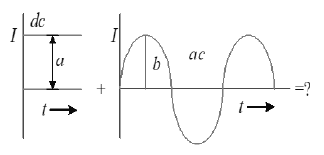
Sol: As current at any instant in the circuit will be,
So,
i.e,
But as
So,
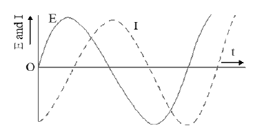
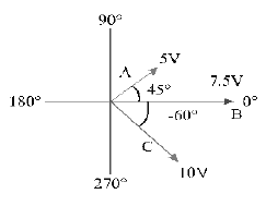
5. Use a phasor diagram to represent the sine waves in the following Figure.
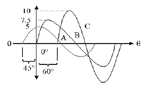
Sol: The phasor diagram representing the sine waves is shown in figure.The length of each phasor represents the peak value of the sine wave.
6. An alternating voltage
volt is connected to a 1 F capacitor through an ac ammeter. What will be the reading of the ammeter?
Sol. Comparing with
7. Find the maximum value of current when a coil of inductance 2H is connected to 150V, 50 cycles / sec supply.
Sol. Here L = 2H, , f = 50 Hz
RMS value of current through the inductor,
Maximum value (or peak value) of current is given by
or
8. An inductor of 1 henry is connected across a 220 v, 50 Hz supply. The peak value of the current is approximately.
Sol. Peak value of current
9. A capacitor of 2 F is connected in a radio circuit. The source frequency is 1000 Hz. If the current through the capacitor branch is 2 mA then the voltage across the capacitor is
Sol.
10. A 0.21 H inductor and a 12 ohm resistance are connected in series to a 220 V. 50 Hz ac source. Calculate the current in the circuit and the phase angle between the current and the source voltage .
Sol. Here
The current will lag the applied voltage by an angle .
11. When 100 volt dc is applied across a coil, a current of 1 amp flows through it; when 100 V ac of 50 Hz is applied to the same coil, only 0.5 amp flows. Calculate the resistance and inductance of the coil.
Sol. In case of a coil, i.e, L – R circuit,
So when dc is applied, = 0, so Z = R
and hence
and when ac of 50 Hz is applied.
but
12. A 10μF capacitor is in series with a 50 resistance and the combination is connected to a 220V, 50 Hz line. Calculate (i) the capacitive reactance, (ii) the impedance of the circuit and (iii) the current in the circuit.
Sol. Here
(i) Capacitive reactance,
(ii) Impedance of CR circuit.
(iii) Current,
13. A coil has an inductance of 0.7 H and is joined in series with a resistance of 220 . When an alternating e.m.f of 220 V at 50 cps is applied to it, then the wattless component of the current in the circuit is :
Sol: As current leads the voltage by ,
or
15. In a series LCR circuit, the voltage across the resistance, capacitance and inductance is 10V each. If the capacitance is short circuited then the voltage across the inductance will be
Sol. As
Z = R; V = IR = 10 volt
When capacitor is short circuited,
New current,
Potential drop across inductance
16. An inductance of . a capacitance of F and a resistance of 10are connected in series with an AC source of 220 V, 50 Hz. The phase angle of the circuit is
Sol. Here,
17. In a series LCR circuit, R = 200, the voltage and the frequency of the main supply is 220 V and 50 Hz. respectively. On taking out the capacitance from the circuit, the current lags behind the voltage by .On taking out the inductor from the circuit, the current leads the voltage by . The power dissipated in the LCR
circuit is
Sol. Here,
In L -R circuit,
In C – R circuit,
In L – C – R circuit, if is the phase difference between voltage and current, then
i.e., current and voltage are in the same phase.
Average power =
18. An LCR circuit has L = 10 mH. R = 3 ohm and C = 1 F connected in series to a source of 15 cost volt. What is average power dissipated per cycle at a frequecny that is 10% lower than the resonant requency?
Sol. Here,
Resonant frequency,
Actual frequency,
Power dissipated / cycle =
19. A 750 Hertz – 20 volt source is connected to a resistance of 100 ohm, an inductance of 0.1803 henry and a cpacitance of 10 F, all in series. What is the time in which the resistance (Thermal capacity = 2 joule/C ) will get heated by 10C ?
Sol. Here,
Power dissipated =
Heat produced in resistance =
If t is the required time, then
20. An ideal choke coil takes a current of 8 ampere when connected to an AC supply of 100 volt and 50 Hz. A pure resistor under the same conditions takes a current of 10 ampere. If the two are connected to an AC supply of 150 volts and 40 Hz. then the current in a series combination of the above resistor and inductor is
Sol: For pure inductor,
For the combination, the supply is 150 v, 40 Hz
21. An electric bulb has a rated power of 50 W at 100 V. If it is used on an AC source of 200 V, 50 Hz, a choke has to be used in series with it. This choke should have an inductance of
Sol: Here, P = 50W, V = 100volt
Let L be the inductance of the choke coil
Now
22. A transformer having efficiency 90% is working on 100 V and at 2.0 kW power. If the current in the secondary coil is 5A, calculate (i) the current in the primary coil and (ii) voltage across the secondary coil.
Sol: Here, ,
23. A step up transformer operates on a 230 V line and a load current of 2 ampere. The ratio of the primary and secondary windings is 1 : 25. What is the current in the primary ?
Sol: Using the relation
Here
and
Current in primary,