


1. ELASTICITY
The property of the body to regain its original configuration (length, volume or shape) when the deforming forces
Elasticity and Plasticity
We know that a body is said to be rigid if the relative positions of its constituent particles remain unchanged, when external forces act on it. Real bodies are not perfectly rigid as all real bodies can be deformed by the application of deforming force. When the deforming forces are removed the bodies regain their original condition due to the restoring forces set up inside the body.
The restoring force in a body is equal and opposite to the deforming force on the body .
The property of a body by virtue of which it regains its original shape or size on removal of the deforming forces is called elasticity.
If a body regains its original condition completely when the deforming forces are removed, then the body is said to be perfectly elastic. In nature, there are no perfect elastic bodies. The nearest approach to a perfectly elastic body is a ‘quartz fiber’.
Plasticity is the property of a body virtue of which it remains in the deformed state even after the deforming forces are removed.
If a body completely retains its modified position after the removal of the deforming forces, then the body is said to be perfectly plastic. In nature, there are no perfect plastic bodies. The nearest approach to a perfect plastic body is putty. Some other examples of nearly perfectly plastic bodies are clay, wax, wheat dough, butter etc.
Real bodies are neither perfect elastic nor perfectly plastic. They are partially elastic.
Terms related to elasticity
1. Deforming force: If a force applied on a body produces a change in the normal positions of the molecules of the body, which results in a change in the configuration of the body either in length, volume of shape, then the force applied is called deforming force. Thus a deforming force is one which when applied changes the configuration of the body.
2. Perfectly elastic body: A body which regains its original configuration immediately and completely after the removal of deforming force from it, is called perfectly elastic body. Quartz and phosphor bronze are the examples of nearly perfectly elastic bodies.
3. Perfectly plastic body: A body which does not regain its original configuration at all on the removal of deforming force, howsoever small the deforming force may be, is called perfectly plastic body.
Putty and paraffin wax are the examples perfectly plastic bodies.
In fact no body is perfectly elastic or perfectly plastic. Only the degree of elasticity of plasticity differs with the body.
2. STRESS & STRAIN
Stress
When a deforming force is applied on a body, it changes the configuration of the body by changing the normal positions of the molecules or atoms of the body. As a result, an internal restoring force comes into play which tends to bring the body back to its initial configuration. This internal restoring force acting per unit area of a deformed body is called stress i.e.
If there is no permanent change in the configuration of the body (i.e. in the absence of plastic behaviour of the body), the restoring force is equal and opposite to the external deforming force applied. Thus quantitatively, stress can be given as
………. (1)
Units of stress: The unit of stress in S.I. system is Nm–2 and in cgs system is dyne/cm2. The dimensional formula stress is ML-1T-2.
Types of stress
i) Normal stress: When a deforming force acts normally over an area of a body, then the internal restoring force setup per unit area of the body is called normal stress.
Normal stress can be subdivided into two categories.
a) Tensile stress: If there is an increase in the length or extension of the body in the direction of force applied, the stress set up is called tensile stress.
b) Compression stress: If there is a decreases in length of wire or compression of the body due to force applied, the stress set up is called compression stress.
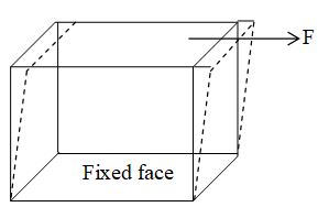
ii) Tangential stress: When a deforming force, acting tangentially to the surface of a body produces a change in the shape of the body, then the stress setup in the body is called tangential stress.
If a tangential force F applied on the top face of area a of a cubical body whose bottom face is rigidly fixed, changes the shape of the cubical body, without changing its volume, then
Tangential stress =
Strain
When a deforming force is applied on a body there is a change in the configuration of the body. The body is said to be strained or deformed. The ratio of change in configuration to the original configuration is called strain i.e.
…….. (2)
Strain being the ratio of two like quantities has no units and dimensions.
Types of strain
As the change in configuration involves a change either in length, volume or shape of the body, hence the strain is of three types.
i) Longitudinal strain: If the deforming force produces a change in length alone, the strain produced in the body is called longitudinal strain or tensile strain. It is defined as follows:
ii) Volumetric strain: If the deforming force produces a change in volume alone, the strain produced in the body is called volumetric strain. It is defined as follows
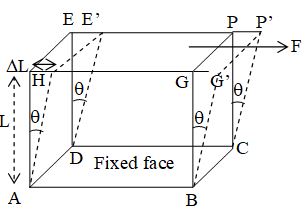
iii) Shearing strain: If the deforming force produces a change in the shape of the body without changing its volume, the strain produced is called shearing strain. It is defined as angle in radian through which a plane perpendicular to the fixed surface of the cubical body gets turned under the effect of tangential force.
Consider a cubical body as shown in figure. Its lower surface ABCD is fixed and a tangential force F is applied on the top surface EPGH. Let the vertical planes AHED and BCPG be laterally shifted to positions AH’E’D and BCP’G’ respectively, through an angle θ where, HAH’ = θ, Let HA=L and HH’ = L.
Thus the shearing strain is also defined as the ratio of displacement of a surface under a tangential force to the perpendicular distance of the displaced surface from the fixed surface.
3. ELASTIC LIMIT & HOOKE’S LAW
Elastic Limit
Elastic limit is the upper limit of deforming force up to which, if deforming force is removed, the body regains its original form completely and beyond which if deforming force is increased, the body loses its property of elasticity and gets permanently deformed.
Hooke’s law
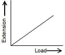
From the experimental study made by Hooke in connection with the extension produced in the wire and load applied, he formulated a law known as Hooke’s law.
Hooke’s law states that the extension produced in the wire is directly proportional to the load applied within elastic limit i.e. within elastic limit, extension load applied.
Later on, it was found that this law is applicable to all types of deformations such as compression, bending twisting etc. and thus a modified form of Hooke’s law was given as stated below:
Within elastic limit, the stress developed is directly proportional to the strain produced in a body
i.e. stress strain
or stress = E strain
Modulus of elasticity
According to Hooke’s law, within elastic limit
Stress strain
or stress = E strain
or ,
where E is known as coefficient of elasticity or modulus of elasticity of a body which is independent of magnitude of stress and strain but depends upon the nature of material of the body and the manner in which the body is deformed. Thus modulus of elasticity or coefficient of elasticity of a body is defined as the ratio of the stress to the corresponding strain produced, within the elastic limit.
4. TYPES OF MODULUS OF ELASTICITY
For a given material there can be different types of modulus of elasticity depending upon the type of stress applied and the resulting strain produced. Corresponding to three types of strain, there are three types of modulus of elasticity, as described below:
Young’s modulus of elasticity (y)
It is defined as the ratio of normal stress to the longitudinal strain within the elastic limit. Thus
…….. (3)
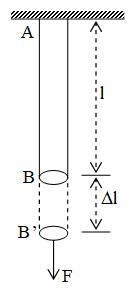
Consider a metal wire AB of length l, radius r and of uniform area of cross-section a. Let it be suspended from a rigid support at A. Let a normal force F be applied at its free end B and let its length increased by (=BB’).
Then, longitudinal strain =
Normal stress =
Units: The unit of Young’s modulus of elasticity in S.I. is Nm-2 or Pascal (denoted by Pa) and in cgs system is dyne/cm2. Its dimensional formula is ML-1T-2.
Bulk modulus of elasticity (k)
It is defined as the ratio of normal stress to the volumetric strain, within the elastic limit. Thus
…….. (4)
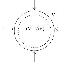
Consider a spherical solid body of volume V and surface area a. In order to compress the body, let a force F be applied normally on the entire surface of the body and its volume decreases by V, then
Volumetric strain =
Here negative sign shows that volume is decreasing when force is applied
Normal stress =
If p is the increase in pressure applied on the spherical body then
Units: The units of bulk modulus of elasticity in S.I. is Nm-2 or Pascal (denoted by Pa) and in cgs system is dyne/cm2. Its dimensional formula is ML–1T–2.
Compressibility(C) of a material is the reciprocal of its bulk modulus of elasticity (K) i.e..
S.I. unit of compressibility is N-1 m2 and cgs unit is dyne-1 cm2.
Modulus of rigidity ()
It is defined as the ratio of tangential stress to the shearing strain, within the elastic limit. It is also called shear modulus of rigidity. Thus
Consider a solid metal cube ABCDEPGH whose each side is of length L. Let its lower face ABCD be fixed and a force F be applied tangentially to the top face EPGH. As a reaction, an equal and opposite force F will be set up on the lower fixed face and a couple will be formed by these forces. Due to this the body will not change its volume but will suffer a change in its shape. Let the vertical planes ADEH and BCPG be shifted laterally to positions ADE’H’ and BCP’G’, through and angle θ i.e.
Let HH’ = L
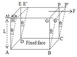
Shearing strain =
Tangential stress =
Units: The unit of h in S.I. is Nm-2 or Pascal (denoted by Pa) and in cgs system is dyne/cm2. Its dimensional formula is ML–1T–2.
5. STRESS-STRAIN RELATIONSHIP IN A WIRE
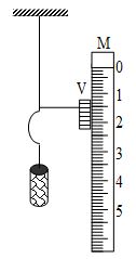
Suspend a wire of uniform area of cross-section vertically from a rigid support through one end and attach a hanger at the other end of the wire on which known weights can be placed. Attach vernier scale V to the lower end of the wire which can slide over a main scale M. Put the different known weights in the hanger and note down the corresponding extensions produced in the wire. Calculate the stress and strain for various observations.
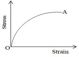
Plot a graph between stress and strain for the stretched wire under observations. We shall get a curve of the type as shown in the figure. From this curve we not the following.
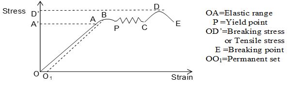
i) The portion OA of the graph is a straight line, showing that stress is directly proportional to strain up to a stage represented by point A on the graph. Thus Hooke’s law is fully obeyed in the region OA. If the wire is unloaded at stage A, it regains its original length completely corresponding to point O by retracing the path AO. Here, the point A corresponds to elastic limit and OA represents elastic range.
ii) Beyond A, the graph is not a straight line but a curved line from A to P. In this region, a small increase in stress shows a comparatively larger increase in strain. If the wire is unloaded at point B, the graph between stress and strain will not follow the path BAO but it traces a dotted line BO1. This indicates that when stress = zero, strain = OO1. So a permanent strain represented by OO1 is produced in the wire which is called permanent set. In the portion ABP of the graph, Hooke’s law fails and the extension in the wire is partly elastic and partly plastic in behaviour.
iii) Beyond point P, the graph is represented by irregular wavy line from P to C. Here, the wire shows increase in strain without any increase in stress. It means the wire begins to flow down after point P, without any increase in stress and it continues up to point C. The point P at which the wire yields to the applied stress and begins to flow down is called yield point. The behaviour of the wire corresponding to the portion of graph from P to C is perfectly plastic.
iv) Beyond point C, the graph is curved line CDE. It shows that if the wire is loaded by a little load beyond P, the thinning of the wire starts and the necks and waists (i.e. constrictions) are developed at few weaker portions in the wire and finally the wire breaks there which is shown by point E. The stress corresponding to point D is called breaking stress or ultimate stress or tensile stress of the wire.
Classification of materials from the study of stress versus strain curve:
From the study of stress-strain variation, the different materials can be classified as explained below.
1. Ductile materials: These are those materials which show large plastic range, beyond elastic limit. For such materials, the breaking point is widely separated from the point of elastic limit on the stress-strain graph. Such materials can be used in making springs and sheets. Examples of ductile materials are copper, silver, iron, aluminium etc.
2. Brittle materials: These are those materials which show very small plastic range beyond elastic limit. For such materials, the breaking point lies close to the elastic limit. Such materials cannot be used in making the springs and sheets examples or brittle materials are cast iron glass etc. The stress-strain curve for a brittle material is shown.
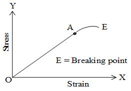
3. Elastomers: These are those materials for which stress and strain variation is not a straight line within elastic limit and strain produced is much larger than the stress applied. Such materials have no plastic range. The breaking point lies just close to the elastic limit. Examples are rubber, the elastic tissue of arota, the large vessel carrying blood from hart etc. The variation of stress and strain for an elastomer has been shown in the given figure.
Note:
1. Breaking force = breaking stress ´ area of cross section of the wire
2. Note that breaking stress is fixed for a material, but breaking force will vary, depending on area of cross section of the wire.
3. While using the material, the working stress is always kept much lower than that of breaking stress so that safety factor (=breaking stress/working stress) may have a large value.
Elastic after effect
We know that on removing the deforming forces from the elastic bodies, they regain their original configuration. Some elastic bodies regain their original configuration immediately, but a few others take some time to recover their original configurations. The temporary delay in regarding the original configuration by an elastic body after the removal of a deforming force is called elastic after effect. The elastic after effect is negligibly small for quartz and phosphor bronze, but very large for glass fibre. It is due to this reason that the suspensions, made from quartz or phosphor bronze are used in moving coil galvanometers.
Elastic fatigue
When an elastic body is subjected repeatedly to the action of alternating deforming forces, its behavior corresponds to that of less elastic bodies. For example, suppose we have two exactly identical wires. A and B, fixed to a rigid support and carrying two similar discs at their free ends. Let the disc attached to A be given repeated torsional vibrations about the wire for a few days, whereas the disc attached to B is kept at rest. Now let both the discs be given similar vibrations simultaneously. It is observed that the vibrations of B last longer, whereas that of A die soon. Clearly, the wire A must have been tired or fatigued because of its vibrations prior to the vibrations of B.
Hence elastic fatigue is the property of an elastic body by virtue of which its behavior becomes less elastic under the action of repeated alternating deforming forces.
It may be interest to note that elastic fatigue corresponds to the physical fatigue in human beings. Just as a tired person is normal after taking due rest, the elastic body is also relieved of the fatigue or regains its original degree of elasticity, when allowed to rest for some time.
6. APPLICATIONS OF ELASTICITY
1. The metallic parts of the machinery are never subjected to a stress beyond elastic limit, otherwise they will get permanently deformed.
2. The crane which is used to lift and move the heavy load is provided with thick and strong metallic ropes to which the load to be lifted is attached. The rope is pulled by using pulleys and motor. The thickness of the metallic rope used in the crane in order to lift a given load is decided from the knowledge of elastic limit of the material of the rope and the factor of safety.
3. The bridges are designed in such a way that they do not bend much or break under the load of heavy traffic, force of strongly blowing wind and its own weight.
4. Maximum height of a mountain on earth can be estimated from the elastic behavior of earth.
7. ELASTIC POTENTIAL ENERGY IN A STRETCHED WIRE
When a wire is stretched, some work is done against the internal restoring forces acting between particles of the wire. This work done appears as elastic potential energy in the wire.
Consider a wire of length l and area of cross section a. Let F be the stretching force applied on the wire and l be the increase in length of the wire. Initially, the internal restoring force was zero but when length is increased by l, the internal force increases from 0 to F (=applied force). Thus average internal force for an increase in length l of the wire =
Hence, work done on the wire, W = average force increase in length =
This is stored as elastic potential energy U in the wire
=
Elastic potential energy per unit volume of the wire
Note: Interatomic force constant K (i.e. restoring force per unit extension of wire) is equal to the product of Young’s modulus of the material of the wire, Y and normal distance ro between the atoms of the wire i.e. K = Yro.
8. POISSON’S RATIO
When a deforming force is applied at the free end of a suspended wire of length l and radius R, then its length increases by but its radius decreases by R. Now two types of strains are produced by a single force
i) Longitudinal strain =
ii) Lateral strain = –R/R
then, the Poisson’s ratio,
Here negative sign shows that if the length increases, then the radius of wire decreases. Poisson’s ratio is a unit less and dimensionless quantity.
Note: Practical value of Poisson’s ratio lies between zero and 0.5.
Relation between y, k, and
1. Y = 3K(1-2)
2. Y = 2h(1+)
3.
4.
9. THERMAL STRESSES
When a rod is rigidly fixed at its two ends and its temperature is changed, then a thermal stress is set up in the rod, which is given by
Thermal stress =
where is the coefficient of linear expansion of the rod and is the change in temperature of the rod.
When the temperature of a gas enclosed in a vessel of any rigid material is changed, then the thermal stress produced is equal to change in pressure (P) of the gas and is given by
where K is the bulk modulus of elasticity of the gas and is the coefficient of cubical expansion of the gas.
10. EFFECT OF COMPRESSION ON THE DENSITY OF LIQUID
Density of liquid r of given mass m and volume V is given by
Taking log of both sides we have
log = log m – logV
differentiating it, we have
. . . . (i)
Bulk modulus of elasticity
or
so,
if ’ is the density of the given liquid when pressure is increased by amount P on it, then
so,
or,
Where C is the compressibility of the liquid.
11. EXPERIMENTAL DETERMINATION OF YOUNG’S MODULUS (Y) – SEARLE’S APPARATUS
Young’s modulus of the material of a wire can be experimentally determined by Searle’s method.
Description
Two wires of the same material, length and area of cross section, suspended from a rigid support carry at their lower ends, two rectangular metal frames as shown in fig. One of the wires is called experimental wire and the other wire is called reference wire. The frame attached to the reference wire carries a constant weight to kept the wire stretched without any kinks. The frame attached to the experimental wire carries a hanger, over which slotted weights can be slipped as required. A spirit level is hinged with one end to the frame attached to the reference wire and rests horizontally on the tip of a micrometer screw which can be worked in the frame attached to the experimental wire along a vertical scale marked in millimeter.
Working
1. A suitable load is kept on the hanger so that the experimental wire is straight without kinks.
2. The micrometer screw is adjusted so that the air bubble in the sprit level comes in the centre. The reading of the micrometer screw is noted.
3. Half a kilogram weight is then slipped into the hanger. This elongates the experimental wire. The frame attached to the experimental wire moves down relative to the other frame and the air bubble shifts to one side. The micrometer screw is now adjusted to take back the air bubble to the centre and the micrometer screw reading is noted.
4. The experiment is repeated at least five times every time increasing the load by half a kilogram weight. Readings of the micrometer screw are noted while increasing and decreasing the load and mean reading is found.
5. The difference between the first and second readings gives the increase in length or extension produced in the experimental wire when the load is increased by half a kilogram weight. The difference between the first and third readings gives the extension for a load of one kilogram weight. Similarly, the extensions for , 2, …. Kg wt are found.
6. A graph is plotted between the load and extension. The graph is a straight line and gives the elongation a for a load Mg.
7. The radius, r of the experimental wire is found by using a screw gauge and measuring the diameter at 6 or 7 places of the wire. The length, L, of the experimental wire is measured with the help of a meter scale.
8. Substituting the values of r, L and Mg/e in the formula of Young’s modulus.
the Young’s modulus of the material is calculated.
SOLVED EXAMPLES
1. A steel wire of length 6m and diameter 4 mm is stretched by 5kg-wt force. Find the increase in its length, if the Young’s modulus of steel wire is 2.01012 dyne/cm2.
Sol. Here,
= 6m = 600 cm;
2r = 4 mm or r = 2.0 mm = 0.20 cm;
F = 5 kg wt = 5000 g-wt. = 5000 980 dynes
l = ?; Y = 2.01012 dyne/cm2
as
or
2. The ratio of radii of two wires of same material is 2 : 1. If these wires are stretched by equal force, find the ratio of stresses produced in them.
Sol. Here r1 : r2 = 2:1
F1 = F2 = F
Stress(S) =
Therefore
Hence
3. When the pressure on a sphere is increased by 80 atmospheres then its volume decreases by 0.01%. Find the bulk modulus of elasticity of the material of sphere.
Sol. Here, p = 80 atmospheres
= 8.11010 N/m2.
4. A 5 cm cube has its upper face displaced by 0.3 cm by a tangential force of 10N. Calculate the shearing strain, shearing stress and modulus of rigidity of the material of cube.
Sol. L = 5cm = 510-2 m;
L = 0.3 cm = 0.310-2 m; F = 10N;
Shearing strain =
Shearing stress =
Modulus of rigidity, .
5. A steel wire of 4.0 m in length is stretched through 2.0 mm. The cross-sectional area of the wire is 2.0 mm2. If Young’s modulus of steel is 2.01011 N/m2 find (i) the energy density of wire (ii) the elastic potential energy stored in the wire.
Sol. Here, l = 4.0 m;
l = 210-3 m; a =2.010-6 m2
Y = 2.01011 N/m2
i) The energy density of stretched wire
=
ii) Elastic potential energy = energy density ´ volume
= 2.5104(2.010-6)4.0 J = 20 10–2
= 0.20 J
6. A steel wire of length 1m, mass 0.1 kg and uniform cross sectional area 10-6m2 is rigidly fixed at both ends. The temperature of the wire is lowered by 20°C. If transverse waves are set up by plucking the wire in the middle, what is the frequency of the fundamental mode of vibration? (Young’s modulus of steel = 2.01011 N/m2, coefficient of linear expansion of steel = 1.2110-5 per °C)
Sol: The frequency of the fundamental mode of vibration is given by the formula
, where T is the tension.
The force of tension is provided by the contraction due to the decrease in temperature.
Contraction =
Now, Y =
7. A metal rod of co-efficient of linear expansion has its temperature raised by . Find the linear compressive stress to prevent the expansion of the rod.
Sol: dynes/m2
Expected charge in length due to temperature increase
Hence stress required to prevent this expansion
=
8. A steel rod of cross sectional area 4 cm2 and length 2m shrinks by 0.1 cm as the temperature decreases in night. If the rod is clamped at both ends along the day hours. The tension developed in the wire will be__.
If y steel = 1.91011 N/m2
Sol. =
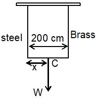
9. A light rod of length 200 cm is suspended from the ceiling horizontally by means of two vertical wires of equal length tied to its ends. One of the wires is made of steel and is of cross-sectional area 0.1 cm2 and the other is of brass of cross-sectional area 0.2 cm2. For what value of x. Where a body of mass m is suspended such that stress in both the wires will be equal?
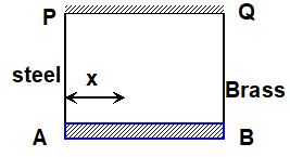
Ysteel = 201011 dynes/cm2 and YBrass = 101011 dynes/cm2.
Sol. Let a weight W be suspended from a point C on the rod such that it is x cm from the steel wire. Let the forces in steel & brass wires be F1 and F2 respectively.
Stress developed in steel wire = F1/0.1 = 10 F1 dynes/cm2
Stress developed in brass wire = F2/ 0.2 = 5F2 dynes/cm2
Now if strain are equal, then
. . . (ii)
From (i) and (ii), .
10. In the above example for what value of x strains in both the wires will be equal?
Ysteel = 201011 dynes/cm2 and YBrass = 101011 dynes/cm2.
Sol. Let the weight w be hung at a point y cm away from the steel wire and forces developed in the steel & brass wires be F3 and F4 respectively.
. . . (iii)
Strain in steel wire = strain in brass wire
or . . . (iv)
From (iii) and (iv), x = 100 cm.