


1. INTRODUCTION
Light form of energy gives sensation of sight. Study of all aspects of light related to rectilinear propagation of light is Ray Optics. Traveling of light along straight line in a homogeneous medium is known as rectilinear propagation of light. Lenses and mirrors using principles of reflection and refraction are used in the study of Ray Optics. This subject is also known as Geometrical Optics.
2. NATURE OF LIGHT
Early theories considered light to be a stream of particles which emanated from a source and caused the sensation of vision upon entering the eye. The most influential proponent of this particle theory of light was Newton. Newton’s opined that light was a flux of tiny particles called corpuscles.
Newton’s corpuscular theory:
A source of light continuously emits corpuscles in all directions. These particles are elastic and travel in straight lines with an enormous velocity. Corpuscles produce sensation of vision when they fall on the retina of the eye. Using it, Newton was able to explain the laws of reflection and refraction, but this theory couldn’t explain the phenomenon of interference, diffraction, polarization etc.
The following are certain conclusions of corpuscular theory which are against the experimentally observed facts.
i) This theory assumes that the source of light looses mass as it emits corpuscles; but no such decrement in mass of the source of light is detected.
ii) According to this theory the velocity of light in denser medium should be greater than that in air. This assumption was proved wrong by Focault’s experiment conducted to measure the speed of light.
iii) This theory proposes that velocity of the corpuscles increases as the temperature of the source increases. Experiments have proved that the velocity of light is independent of temperature.
3. FOUR LAWS USED IN THE STUDY OF GEOMETRICAL OPTICS
1. Law of Rectilinear propagation of light
It states that light propagates in straight lines in homogenous media.
2. Law of Independence of light rays:
It states that rays do not disturb each other upon intersection
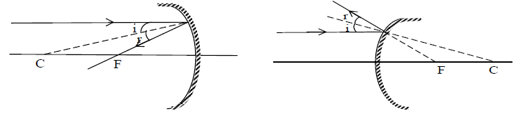
3. Laws of Reflection:
i) The incident ray, the reflected ray and the normal to the reflecting surface at the point of incidence all lie in the same plane.
ii) The angle of reflection (r) is equal to the angle of incidence (i) i.e, i = r.
These laws are applicable to all reflecting surfaces either plane or curved. Fig : Law of reflection for plane and curved surfaces.
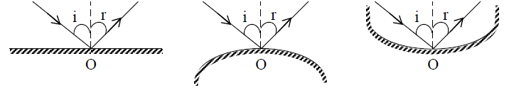
Case – I: If i = 0, by i = r, r = 0, if a ray is incident normally on a boundary, after reflection it retraces its path.
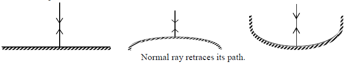
4. LAWS OF REFRACTION
i) The incident ray, the refracted ray and normal to the interface at the point of incidence lie in the same plane i.e, they all are co-planar
ii) The ratio of the sine of the angle of incidence (i) and that of the angle of refraction (r) is a constant for any two given media.
i.e. = constant …. (i)
This law is known as Snell’s law.
This constant is known as the refractive index of the second medium (in which refracted ray propagates) with respect to the first medium (in which incidence ray propagates) .
Therefore equation (i) can be written as .
The refractive index of a substance relative to vacuum (a ray passes through the vacuum to the given medium) is called absolute refractive index of the substance. If μ1 and μ2 are the absolute refractive index of first and the second media respectively.
Then
This equation gives generalized Snell’s law of reflection.
When light propagate through a series of layers of different media as shown in the figure, then the Snell’s law may be written as
In general
Absolute refractive index:
The absolute refractive index of a medium is defined as the ratio of the speed of light in vacuum to the speed of light in the medium
Case–I : If
i.e., when light passes from rarer to denser medium it bends towards away the normal.
Case-II: If
i.e., when light passes from denser to rarer medium it bends away from the medium.
Case–III: If
i.e., the light ray is not refracted and the boundary between the two medium is not visible. This is why a transparent solid is invisible in a liquid of same refractive index.
Case–IV: If
If light is incident normal to a boundary then it passes undeviated from the boundary.
5. REFLECTION OF LIGHT BY A PLANE MIRROR
The following properties of a plane mirror are worth mentioning
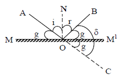
1. Deviation of light by plane mirror: A plane mirror can be used to deviate light from one direction to another. The angle AOM made by incident ray AO with MM| is known as the glancing angle (g) with the mirror.
Angle of deviation =
( i = r )
Hence the angle of deviation of a ray by a plane mirror is twice the glancing angle or a ray is deviated through an angle
2. When plane mirror is rotated through a certain angle θ, then the reflected ray turns through an angle 2θ.
3. If the plane mirror moves away or towards an object by a distance d, then the image moves away or towards the object by a distance 2d.
4. If the mirror moves with speed ‘u’ towards or away from a fixed object, then the image appears to move towards or away from the object with speed 2u.
5. If the object moves with speed ‘u’ towards mirror. The image also moves towards the mirror with speed ‘u’. The speed of the image relative to the object in this case is 2u.
6. The image formed by plane mirror is virtual, erect and laterally inverted.
7. The magnification of plane mirror is 1 i.e., size of object = size of image.
8. The left side of an object appears as the right side of the image.
9. Power of a plane mirror is zero.
10. When two plane mirrors are kept facing to each other at an angle and an object is placed between them, multiple images of the object are formed as of multiple successive reflection.
a. If = an even number. Then number of image is given by – 1
b. If = odd number, then number of images (n) is decided according to two situations
I). If the object lies symmetrically, then n =
II). If the object lies asymmetrically, then n =
c) When two plane mirrors are placed parallel to each other then
11.
a) The minimum size of the mirror required to see full size image of one self is equal to half the height of the observer.
b) The minimum size of the mirror required to be fixed on the wall of a room, so that an observer in the middle of the room can see full image of wall behind him is of the height of the wall.
12. Reflection from a denser medium causes a phase difference of π.
Illustration 1: Two plane mirrors M1 and M2 are inclined at angle. A ray of light, which is parallel to M1 strikes M2 and after two reflections, the ray becomes parallel to M2. Find the angle.
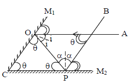
Solution. Since PB || OM1
and OA || to PM2
In
Illustration 2: A ray of light passes from air to glass (μ = 1.5) at an angle of 300. Calculate angle of refraction. What is the speed of right in glass?
Solution. As
As
6. REFLECTION FROM A PLANE MIRROR
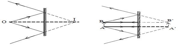
Almost every body is familiar with the image formed by a plane mirror. If the object is real, the image formed by a plane mirror is virtual, erect and at the same distance from the mirror. The ray diagram of the image of a point object and of an extended object is as shown below.
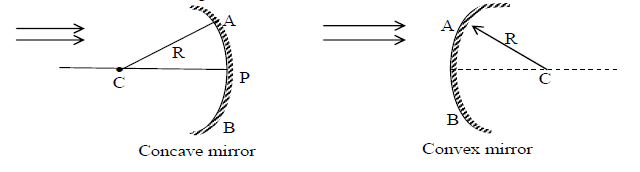
7. REFLECTION FROM A SPHERICAL SURFACE There are two types of spherical mirrors, concave and convex. If the light is reflected from the inside surface of a sphere then it is called Concave mirror. If the light is reflected from the outer surface of a sphere then it is called convex mirror as shown in fig.
Terms and Definitions:
i) Centre of curvature: The centre ‘C’ of the sphere of which mirror is apart of sphere is called Centre of curvature of the mirror.
ii) Pole of the mirror: The centre ‘P’ of the mirror surface is called pole of the mirror.
iii) Radius of curvature: The radius of the sphere of which the mirror is a part is called Radius curvature.
iv) Principal axis: It is a straight line joining the pole (P) and centre of curvature (C) extended on both sides.
v) Aperture: The surface of mirror from which reflection is occurs called Aperture. “AB” is the Aperture of the mirror.
vi) Focus: When a narrow beam of ray of light, parallel to the principal axis and close to it is incident on the surface of a mirror, the reflected beam is found to converge to or appears to diverge from a point on the principal axis, is called principal focus.
vii) Focal length of mirror: It is the distance between pole and principal focus.
viii) Real image: If reflected (or refracted) rays converge at a point (i.e., intersect there), the point is a real image.
ix) Virtual image: If reflected (or refracted) rays appear to diverge from a point, the point is a virtual image.
x) Real object: If the incident rays diverge from a point, the point is a real object.
xi) Virtual object: If the incident rays converge and appear to intersect at a point behind the mirror. The point is a virtual object.
xii) Paraxial rays: Rays which are close to principal axis and make small angles with it i.e., they are nearly parallel to the axis, are called paraxial rays.
8. RELATION BETWEEN F AND R:
A ray AM parallel to the principal axis of a concave mirror of small aperture is reflected through the principal focus F. If C is the centre of curvature, CM is normal to the mirror at M because the radius of a spherical surface is perpendicular to the surface.
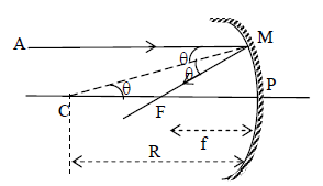
From first law of reflection or,
(alternate angles)
Therefore, ΔFCM is thus isosceles with FC = FM. The rays are paraxial and so M is very close to P.
Therefore
9. IMPORTANT RAY PATHS
Of all the possible rays we could draw from a single point on an object. There are four rays that are particularly useful in locating the corresponding image point. 1. A ray passing parallel to principle axis after reflection from the mirror passes or appear to pass through its focus.
2. A ray initially passing through or directed towards focus after reflection from the mirror becomes parallel to the principal axis.
3. A ray initially passing through or directed towards centre of curvature, after reflection from the mirror retraces its path.
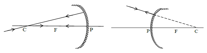
4. Incident and reflected rays at the pole of a mirror are symmetrical about the principal axis (As for pole principle axis acts as normal and from laws of reflection i = r)
10. MIRROR FORMULA
Consider a point object ‘O’ placed on the principal axis of a concave mirror as shown in fig.
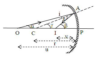
Applying geometry, we get
In ΔOCA, γ = α + i
In ΔCAl, β = γ + r
Since i = r (law of reflection)
∴ α + β = 2γ ———————- [ 1 ]
Applying paraxial approximation
Thus from eq (1) we get,
Using Cartesian sign conventionIn the case of concave mirror
A similar formula can be obtained for convex mirror.
11. LINEAR MAGNIFICATION (M)
Linear magnification (or simply magnification) produced by a spherical mirror is the ratio of size of the image formed by the mirror and the size of the object
i.e,
Linear (Lateral) Magnification (m) =
Longitudinal Magnification:
If an object is placed with its length along the principal axis then longitudinal magnification is defined as the ratio of length of image to length of object
Important points: 1. For real extended objects, if the image formed by a single mirror is erect it is always virtual and in this situation if the size of the image is
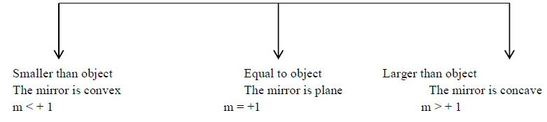
2. For real extended object, if the image formed by a single mirror is inverted, it is always real (i.e, m is –ve) and the mirror is concave. In this situation if the size of image is Smaller than object equal
Equal to the object Object is between ∞ and C
and image is at C and image between F and C.
3. Every part of a mirror forms complete image. If some portion of a mirror is obstructed (say covered with black paper), then complete image will be formed but intensity will be reduced.
4. If an object is moved at constant speed towards a concave mirror from infinity to focus, the image will move (slower in the beginning and faster later on) away from the mirror. This is because in the time object moves from ∞ to C. The image will move from F to C and when object moves from C to F. The image will move from C to. At C the speed of object and image will be equal.
5. Focal length of a spherical mirror is independent of wave length of light and refractive index of medium so the focal length of a spherical mirror in air or water and for red or blue light is same. This is also why the image formed by mirrors do not show chromatic aberration.
6. In case of spherical mirrors if object distance (x1) and image distance (x2) are measured from focus instead of pole.
. So the mirror formulae
reduces to , which on simplification gives which is result is called Newton’s formula.
7. In case of spherical mirrors if we plot a graph between
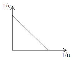
a) and the graph will be a straight line with intercept with each axis a
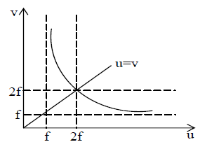
b) u and v the graph will be a hyperbola as u = f, v = ∞ and for u = ∞, v = f. A line u = v will cut this hyperbola at (2f, 2f). This all is shown
12. IMAGE FORMATION BY SPHERICAL MIRRORS
Image formation by a concave mirror, convex mirror are given below in tabular form.
a) For Concave Mirror:
| S.No. | Position of Object | Details of image |
| 1 | At infinity | Real inverted, very small (m<< -1), at F |
| 2 | Between ∞ and C | Real inverted, diminished (m< -1), between F and C |
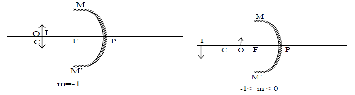
| 3 | At C | Real, inverted, equal (m = -1); at C |
| 4 | Between F and C | Real, inverted, very large (m<< -1), between F and C |
| 5 | At F | Real , inverted, very large, (m>> – 1), at infinity |
| 6 | Between F and P | Virtual erect enlarged (m> +1) behind the mirror |
b) For Convex Mirror
| S.No. | Position of Object | Details of image |
| 1 | At infinity | Virtual , erect , very small (m<< +1) at F |
| 2 | Infront of mirror (not too far from mirror) | Virtual, erect, small between P and C |
Uses of mirrors:
The uses of plane, concave and convex mirrors are given below in tabular form.
| Plane mirror | Concave mirror | Convex mirror |
| i) As a looking glass | Reflecting telescope | Driving mirror |
| ii) Barber’s shop to see back of your head | Dental mirror | Safe view at dangerous corners |
| iii) Periscope | Make–up and shaving mirror | Anti shoplifting device |
Illustration 3: An object is placed 10cm in front of a concave mirror of focal length 15cm.
Find the (i) image position and (ii) magnification
Solution. Here f = -15 cm, u = -10 cm
By mirror formula
v = 30 cm
Since v is positive in sign, the image is virtual erect w.r.t. object.
Linear magnification m =
Therefore, the image is three times as high as the object
New Cartesian sign convention:
To specify the position of the object and image, we need a reference point and sign convention. We shall follow new Cartesian sign convention which is as under
i) All distances are measured from pole of the mirror. (i.e., pole is taken as the origin for measurement of its distance)
ii) The distances measured in the direction of the incident light are taken as positive while those measured in the direction opposite to the incident light are taken as negative.
iii) Height or distance measured upward and perpendicular to the principal axis are considered positive while those measured downwards are considered negative.
Note:
i) The object distance is always negative.
ii) The image distance of the real image is negative while that of the virtual image is positive.
iii) The focal length of concave mirror is negative and that of a convex mirror is positive.
iv) The height of real object and virtual image are positive. However, the height of real image is negative.
Illustration 4: A concave mirror has a radius of curvature 24 cm. How far is an object from the mirror if an image is formed that is
a) real and 3 times the size of the object.
b) virtual and 3 times the size of the object.
Solution. Given R = – 24 cm, f = – 12 cm
a) Image is real and 3 times larger. Hence both u and v are negative, let
u = – x, and v = – 3x
By mirror formula,
x = 16 cm
b) Image is virtual and 3 times larger. Hence u is –ve and v is +ve
Let u = -x , v = 3x
∴ By mirror formulae,
x = 8 cm
Illustration 5: A rod of length 20 cm is placed along the optical axis of a concave mirror of focal length 30 cm. One end of the rod is at the centre of curvature and the other end lies between F and C. Calculate the longitudinal magnification of the rod.
Solution. Let ab is object
Since end a of the rod lies at centre of surface
∴ image of the end a of the rod is formed at its position.
For end b
u = – 40 cm, f = – 30 cm By mirror formula
v = – 120 cm
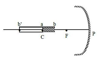
∴ length of image = 120 – 60 = 60 cm
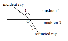
13. PRINCIPLE OF REVERSIBILITY OF LIGHT
According to principle of reversibility of light, if a reflected or refracted ray is reversed in direction it will retrace its original path. Consider an interface XY which separates the two media 1 and 2 having refracting index and respectively. If a plane mirror is placed normal to the path of the refracted ray (OB), then the ray is reversed and retraces the whole path in the opposite direction as shown in fig.
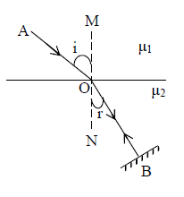
When ray of light travels from medium (1) to medium (2), then according to Snell’s law
…………. [1]
When the path of light is reversed, then ‘r’ will be treated as angle of incidence and i will be treated as angle of refraction.
According to Snell’s law
…….. [ 2 ]
Multiplying eq (1) and (2) we get
Hence the refractive index of medium (1) w.r.to medium (2) is equal to the reciprocal of the refractive index of medium (2) w.r.to medium (1)
14. APPARENT DEPTH AND NORMAL SHIFTING
A point source ‘S’ placed in a medium of refractive index μ is observed from air at a small angle to the normal to the interface between medium and air. If the source is at a depth ‘h’ from the interface, find its apparent position h’, from the interface, as shown in fig.
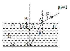
Applying geometry
Since α and β are small,
Therefore ,
Thus ……… [ 1 ]
Using Snell’s law ……… [ 2 ]
From eq (1) and (2)
The apparent shift in the position of the source is
apparent shift =
If there are ‘n’ number of slab with different refractive indices placed between the observer and the object, then the total apparent shift is equal to the summation of all the individual shift.
and apparent depth = , Where represent the heights of liquids.
If the apparent shift comes out to be positive, the image of the object shift toward the observer and vice – versa.
Note:
1) If point object ‘O’ placed in a medium (1) and is observed by someone located in medium (2) then
apparent depth = real depth
Here: ‘1’ indicates medium in which object lies or incidence ray travel. ‘2’ indicate medium in which refracted ray travel or observer lies
2) If the observer is in rarer medium and the object is in denser medium then
apparent depth < real depth
3) If the observer is in denser medium and the object is in rarer medium then
apparent depth > real depth
Lateral shift :
For a small of incidence,
Illustration 6: What is the apparent position of an object below a rectangular block of glass 6cm thick, if a layer of water 4 cm thick is on the top of the glass? Given .
Solution. Here, real depth of glass, x1 = 6cm, real depth of water, x2 = 4cm
If y1, y2 are the corresponding apparent depths,
Then
∴ Rise in position of the object
= (6+4) = (4+3) = 10 – 7 = 3 cm
Illustration 7. A ray of light is incident at an angle of 450 on one face of a rectangular glass slab of thickness 10cm and refractive index 1.5. Calculate the lateral shift produced
Solution: Here, i1 = 450, t = 10cm = 0.1 m
μ = 1.5, lateral shift = ?
As
Lateral shift =
15. TOTAL INTERNAL REFLECTION
Fig. shows a boundary between two media with refractive indices μ1 and μ1 where μ1 > μ2. A ray approaching the boundary from the medium of higher refractive index is refracted away from the normal. For small angle of incidence, there is both a reflected and a refracted rays. But, at a particular angle of incidence (called critical angle θc), the refracted ray emerges parallel to the surface. For any angle of incidence greater than θc the light is totally reflected back into the medium of higher refractive index. The phenomenon is called total internal reflection and was first noted by kepler in 1604.
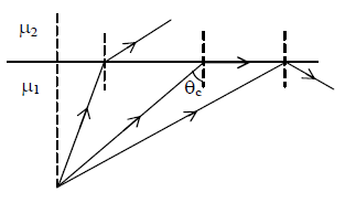
Applying snell’s law
If the rarer medium is air,
The value of critical angle for glass and water are 420 and 48.50 respectively.
Illustration 8: A 2 cm thick layer of water covers a 3 cm thick glass slab. A coin is placed at the bottom of the slab and being observed from the air side along the normal to the surface. Find the apparent position of the coin from the surface
Solution. Here,
We know that apparent depth =
Illustration 9: A small pin fixed on a table top is viewed from above from a distance of 50 cm. By what distance would the pin appear to be raised if it is viewed from the same point through a 15 cm thick glass slab held parallel to the table? Refractive index of glass = 1.5. Will the position of the image effect the answer.
Solution. Normal shifting by slab =
Pin appear to be raised by 5 cm
The location of the slab will not affect the answer in any way.
Illustration 10: Velocity of light in a liquid is m/s and in air, it is . If a ray of light passes from this liquid into air. Calculate the value of the critical angle
Solution. Given
Uses of phenomenon of total internal reflection:
i) In optical instruments such as binoculars in which prisms reflect nearly 100% of the light to make images brighter.
ii) To trap light within a transparent rod even if it is curved.
iii) In optical communication using optical fibres.
iv) Application of Total Internal Reflection (TIR):
There are a large number of partical applications of the phenomenon of total internal reflection. However, only a few applications are discussed below by way of illustration.
1) Total reflecting prism:
A total reflecting prism is a right angled isosceles glass prism. Refractive index of crown glass is . Hence critical angle
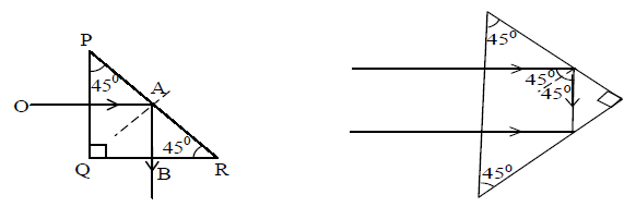
Thus whenever light which is traveling in glass each in incident on such a boundary at an angle more than 420, TIR takes place.
A ray OA incident normally on face PQ of a crown glass prism suffers TIR at face PR since, the angle of incidence in the optically denser medium is 450. A bright ray AB emerges at right angles to face QR. The prism thus, reflects the ray through 900. Light can be reflected through 1800 and an erect image can be obtained of an inverted object if the prism is arranged as shown in fig.
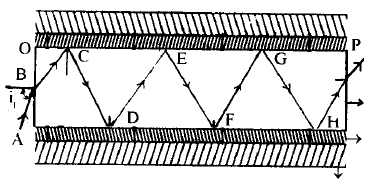
Optical fibres : An optical fiber is a long, hair thin transparent cylindrical rod made of glass or plastic called care which can transmit light between two points. The case in surrounded by another cylindrical shell called cladding. The cladding helps to keep the light within the care through the phenomenon of total internal reflection. The refractive index of care will be slightly greater than that of cladding. Hence the care acts as a denser medium to trap light radiation. The cladding is surrounded by a layer called sheath which protects the optical fiber.
In an optical fiber OP a light ray AB is introduced at an angle i1 known as launching angle. The ray enters the core at ‘B’ with certain refraction and strikes the interface of the core and eladding at C with an angle. Then the ray undergoes total internal reflection and strikes the core-clad-ding interface at D with an angle of incidence greater than the critical angle and undergoes again total internal reflection. This action continues at points E, F, G…… in succession and the ray traverses from one end of the optical fiber to the other end. As there is no refraction of the ray into cladding there is no loss of energy due to refraction.
Uses of optical fiber: Optical fibers are flexible, light-weight and non-corrosive.
i) A single fiber can be used for as many voice channels as a 1500 pair cable can i.e., a single optical fiber can transmit much more information as compared to an ordinary coaxial cable.
ii) Optical fibers are immune to interference from lightning and external electromagnetic radiation.
iii) Telephone conversation can be superposed on the optical beam and transmitted through optical fibers with maximum velocity.
iv) Optical fibers are used in medical equipments such as laproscope and endoscope to observe unreachable parts in human body.
v) Optical fibers are used as sensors in industry to measure temperature, pressure etc.
Illustration 11 Velocity of light in liquid is 1.5 ⨯ 108 m/s and in air, it is 3 ⨯ 108 m/s. If a ray of light passes from liquid into the air, calculate the value of critical angle.
Solution. Here, v = 1.5 ⨯ 108 m/s
c = 3 ⨯ 108 m/s, C = ?
As
C = sin–1 (0.5) = 300
Illustration 12: Determine the critical angle for a glass air surface, if a ray of light, which is incident in air on the surface is deviated through 150, when its angle of incidence is 400.
Solution. Here, C = 7, i = 400, deviation = 150.
As ray deviates towards normal, therefore,
As
Exercise 1:
(i) What is the critical angle for a material of refractive index ?
(ii) Calculate the speed and wavelength of light (a) in glass (b) in air, when light waves of frequency 6 ⨯ 1014 Hz, travel from air to glass of μ = 1.5.
(iii) A pin lying on a table is viewed from a distance of 1 metere. A glass slab of thickness 12cm and μ=1.5 is placed on the pin. What is the distance of the image of the pin from the eye?
(iv) The refractive index of diamond of diamond is 2.47 and that of glass is 1.51. How much faster does light travel in glass than in diamond?
16. THE LENS
A lens is a piece of transparent material bounded by two refracting surface out of which at least one is curved. If thickness of a lens is small and its curved surface is spherical then lens is known as thin spherical lens.
Terms used in lenses
i) Optical Centre (C): The point in the lens through which rays of light pass undeviated.
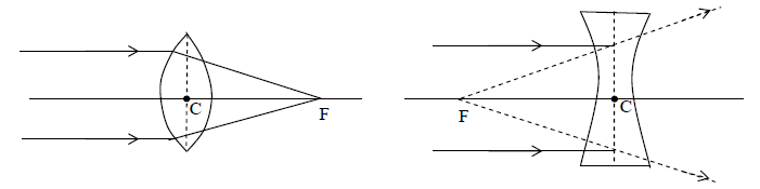
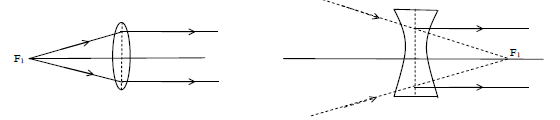
ii) Principal Focus (F): The point on the principal axis where the incident rays of light parallel to the principal axis meet or appear to meet after refracting through a lens is called principal focus
iii) Focal length (f): The distance between the optical centre and principal focus is known as focal length of a lens. Here CF = f
Note: Focal length of a convex lens is positive while that of concave lens is negative
Refraction from a spherical surface:
Consider two transparent media having refractive index μ1 and μ2. Where the boundary between the two media is a spherical surfaces of radius R. We assume that μ1 < μ1. Let us consider a single ray leaving point O and focusing at point I.

The lateral magnification ‘m’ is the ratio of the image height to the object height or. We therefore obtain
Illustration 13: A mark placed on the surface of a sphere is viewed through glass from a position directly opposite. If the diameter of the sphere is 10cm and refractive index of glass is 1.5. Find the position of the image?
Solution. Here, u = – 10cm, R = – 5cm,
μ2 = 1.5, μ1 = 1, v = ?
In the present case refraction occurs from denser to rarer medium,
or
∴ v = – 20 cm.
Illustration 14: Light from a point source in air falls on a spherical glass of μ = 1.5 and R = 0.2m. The image is formed at a distance of 100cm from the glass surface in the direction of incident light. Calculate the object distance from the centre of curvature of the spherical surface.
Solution. Here,
R = 0.2m = 20cm, v = 100cm, u = ?
As refraction occurs from rarer to denser medium,
u = – 100cm
∴ Distance of object from pole of spherical surface is 100 cm.
Distance of object from the centre of spherical surface = 100 + 20 = 120cm.
17. LENS MAKER’S FORMULA
Lens is a piece of transparent material with its sides ground to spherical form. The spherical surfaces may be convex or concave. A biconvex lens is known as converging lens. A biconcave lens is known as diverging lens. Sometimes lenses may have a plane and a spherical surface i.e., we can have plano-convex or plano-concave lenses also.
The line joining the centres of curvature of the two surfaces of a lens is called ‘principal axis’.
The rays traveling parallel to the principal axis’.
The rays traveling parallel to the principal axis when incident on one of the spherical surfaces converge at a point on the other side on the principal axis after refraction. This, point is called ‘principal focus’. A lens has one principal focus on either side of it.
The distance between the optical centre and principal focus is called ‘focal length’.
For a thin lens the relation among the object distance, image distance and focal length is given by
……(1)
This is known as lens formula
Usually a lens is ground to some specific focal length (f) using glass material of known refractive index (μ). Then the radii of curvature of the spherical surfaces R1, R2 are decided according to the equation.
……(2)
Equation is known as lens-maker’s formula. This formula is applicable to thin lenses and hold good only for paraxial rays which subtend very small angles with the principal
Illustration 15: A convex refracting surface of radius of curvature 15 cm separates two media of refractive indices 4/3 and 1.5. An object is kept in the first medium at a distance of 240 cm from the refracting surface. Calculate the position of the image.
Solution. As the object is in the rarer medium
We have
Here u = -240, v = ?, R = +15cm, μ1 = 4/3, μ2 = 3/2
As V is positive, the image is formed in the second medium at a distance ‘d’ 270 cm from the refracting surface. The image is real.
18. LINEAR MAGNIFICATION
The ratio of the size of the image to the size of object is called Linear magnification of the lens.
Let = size of object, size of image formed by lens
Then , linear magnification
Note:
1) Linear magnification in terms of u and f ,
2) Linear magnification in terms of v and f ,
3) If m is positive , i.e., image of a real object is virtual
4) If m is negative, i.e, image of real object is real an inverted.
19. IMAGES FORMED BY THIN LENS
Information as to the position and nature of the image in any case can be obtained either from a ray diagram or by calculation
Ray diagrams: To construct the image of a small object to the axis of a lens, two of the following three rays are drawn from the top of the object
1) A ray parallel to the principal axis after refraction passes through the principal focus or appear to diverge from it.
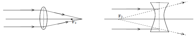
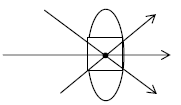
2) A ray through the optical centre p passes undeviated
3) A ray passing through the first focus F1, becomes parallel to the principal axis after refraction.
Keeping the above three points in mind we can show that image formed by a concave lens is always virtual, erect and diminished (like a convex mirror). While the nature of image in case of a convex lens depends on the position of object. The ray diagrams for a convex and a concave lens are shown below
For Convex lens
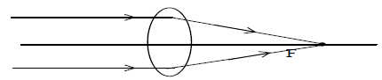
i) When object lies at infinity: The real image is formed at the focus (F) of the lens as shown in fig. The size of the image is very small.
ii) When object lies between infinity and 2F: The real , inverted and diminished image is formed between F and 2F as shown in fig.
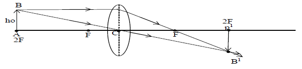
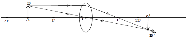
iii) When object lies at 2F : The real and inverted image is formed at 2F. The size of the image is same as that of the object as shown in fig
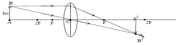
iv) When object lies between F and 2F : The real inverted and enlarged image is formed between 2F and infinity as shown in fig.
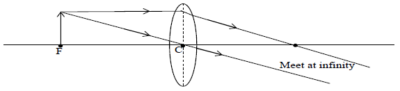
v) When object lies at F : The real , inverted and highly enlarged image is formed at infinity as shown in fig.
vi) When object lies between C and F: The virtual, erect and highly enlarged image is formed on the same side as that of the object (shown in fig)
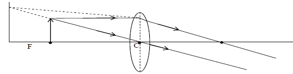
Image formed by a concave lens: The image A’B’ of the object AB formed by concave lens is virtual, erect and diminished. It is formed on the same side as that of the object as shown in the fig (Always virtual and diminished image formed by concave lens)
20. Power of a Lens:
Power of a lens is defined as the reciprocal of the focal length of the lens expressed in meters
i.e,
The focal length of a lens is given by
SI unit of power is dioptre [D]
21. LENSES IN CONTACT
Consider two thin lens of focal length and respectively placed in contact with each other and a point object O is placed at a distance ‘u’ from the combination. The first image (say I1) after refraction from the first lens is formed at a distance v1 from the combination. This image acts as an object for the second lens and let v be the distance of the final image from the combination.
Applying the lens formulae.
for the two lenses we have
……… (1)
……… (2)
Eq (1) + (2), (Say)
Here F is the equivalent focal length of the combination thus
The power of the equivalent focal length is given by
Important Points:
i) a) When two lenses of focal length and are placed co-axially at a distance ‘d’ from each other, then the equivalent focal length is given by and
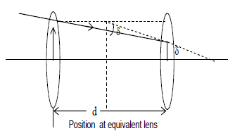
Position of equivalent lens is given by = from 1st lens
b) If Reflective index of the medium between the lens is μ then the equivalent focal length is given by
ii) If I1 and I2 are the length of images in first and second position of lens. ‘O’ is the length of the object , then
iii) When the distance between object and screen d, is greater than uf. Then there are two positions of the lens for which the image of the object on the screen is distinct and clear. In these two positions of lens, the distances of object and image from the lens are interchanged.
If d = distance between object and screen
x = distance between two position of the lens, then focal length
If ‘n’ number of lenses of focal length are jointed together then the equivalent focal length of the combination is given by
In terms of power
iv) Equivalent focal length of lens and mirror combination is given by equation,
Where = focal length of lens, = focal length of mirror
v) When a lens of focal length ‘f’ is cut into two equal halves perpendicular to principal axis, then each part of lens has a focal length ‘2f’. But intensity of transmitted light and aperture of the lens remains the same
vi) When a lens of focal length ‘f’ is cut into two equal haves parallel to principal axis. The each part of lens has a focal length ‘f’ and intensity of transmitted light becomes ½ and aperture of lens becomes of its initial values.
vii) Intensity or brightness of the image is proportional to the square of the aperture of the lens i.e., Intensity of image (Aperture)2 and the brightness of the image produced by a lens which is half painted black reduced to half. However, size of image remains the same.
viii) For working of the optical fibre , the angle of incidence should be according to the following relation Where n1 is the refractive index of the material used for cladding of the pipe and n2 is the refractive index of the bore of the pipe.
Ix) Critical angel increases with the increase in temperature of the medium and depend on the
a) nature of medium b) temperature of medium c) wave length of light
x) Critical angle for red light is more than that for blue light
Illustration 16: A double convex lens made of glass of refractive index 1.56 has both radii of curvature of magnitude 20cm. If an object is placed at a distance of 10 cm from this lens, find the position of image formed.
Solution. Here, μ = 1.56,
R1 = 20 cm, R2 = – 20 cm u = – 10cm, v = ?
As
As
v = – 22.72cm
Illustration 17: Find the focal length and power of a plano convex lens, when radius of curved surface is 15cm and μ = 1.5.
Solution. Here, f = ?, P = ?
R1 = ∞ (for plane surface) R2 = – 15cm, μ = 1.5
As
f = 30 cm.
Illustration 18: A concave lens is kept in contact with a convex lens of focal length 20cm. The combination works as a convex lens of focal length 50cm. Find the power of concave lens
Solution. Here, f1 = + 20 cm,
F = + 50cm, f2 = ?
As
As
Exercise 2:
(i) The refractive index of glass sphere of diameter 10cm is 1.5. Find the position of the image of an object at infinity formed by the sphere.
(ii) The radius of curvature of each face of a biconcave lens, made of glass of refractive index 1.5 is 30 cm. Calculate the focal length of the lens in air
(iii) An object 10 cm long is placed at 15 cm from a convex lens of focal length 10 cm. Find position and size of image.
(iv) The radius of curvature of each surface of a convex lens of refractive index 1.5 is 40 cm. Calculate its power.
(v) Two thin converging lens of focal lengths is cm and 30 cm are held in contact with each other. Calculate power and focal length of the combination.
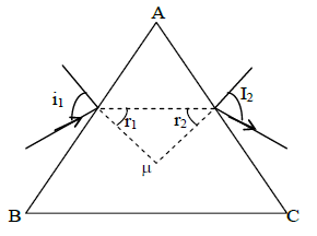
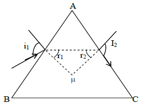
22. PRISM
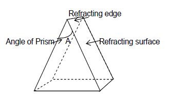
A simple prism is a homogenous refracting medium bounded by at least two non parallel plane surfaces inclined at some angle. Two non parallel plane surfaces participating in refraction of light are called refracting surfaces and the line of intersection of the two refracting surfaces is called refracting edge.
Important Terms
1) The angle between two refracting surfaces is called the angle of prism or refracting angle and is denoted by A
2) Angle of deviation(): The angle between the emergent ray and the direction of incident ray is called angle of deviation.
At surface AB of the prism, Incident ray PQ is deviated along BC
similarly surface AC
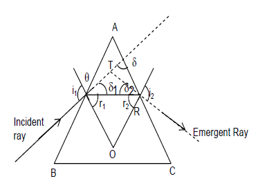
In ΔQRT
…… [ 1 ]
In AQOR
…… [ 2 ]
ΔQOR
……. [ 3 ]
eq (2) and (3)
Condition for no emergence of light from a prism:
The light will not emerge out of a prism for all values of angle of incidence, if angle r2 is greater than critical angle θc for maximum angle of incidence
i1 = 900 i.e, r2 > θc …………… [ 1 ]
Applying snell’s law, for AB in above fig.
or ……………….. [ 2 ]
equation (1) + (2)
or
Thus a ray of light will not emerge out of a prism if A>2θc that is, if
Deviation produced by a very thin prism
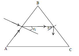
Consider a small angled prism. When the ray of light incident on the face AB of the prism.
We have,
If angle of and is very small
Now, for refraction at the face AC of the prism
Since angle r2 and i2 are very small
The deviation produced by prism is given by
[r1+r2 = A]
Condition for grazing emergence
If a ray can emerge out of a prism, the value of angle of incidence for which angle of emergence
is called the condition of grazing emergence.
As it is obvious from figure
since
Snell’s law for surface AB
……………………… [ 1 ]
That light will emerge out at a prism only if angle of incidence is greater than the condition of grazing emegence by eq (1)
condition
Maximum deviation:
Deviation will be maximum when angle of incidence is maxm (Imax = 900)
……………………… [ 1 ]
When then
And
Thus Snell’s law at second surface
………….. [ 2 ]
eq (1) gives maximum deviation and eq (2) gives Angle of emergence in condition of maximum deviation i.e,
Minimum Deviation:
The angle of deviation by a prism depends on the angle of incidence. The variation of angle of deviation with angle of incidence is shown in fig.
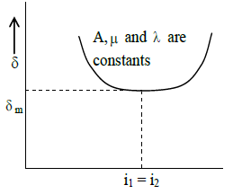
As the angle of incidence of the light increases, angle of deviation decreases till it becomes minimum at a particular angle of incidence. The minimum value of the angle of deviation is called the angle of minimum deviation
There as one and only one angle of incidence for which the deviation produced by the prism is minimum.
Condition for minimum deviation:
Theory and experiment show that will be minimum when the angle of incidence is equal to the angle of emergence i.e.,
Thus minimum deviation is given by
……………………….. ( 1)
Applying snell’s law at each interface, we get
…………………………. (2)
and …………………………. (3)
from (2) & (3)
since from eq (1)
The refractive index of the prism is given by
Illustration 19: A thin prism of 60 angle gives a deviation of 30. What is the refractive index of the material of the prism?
Solution. Here,
We know
or
Illustration 20: The angle of minimum deviation for prism of angle π/3 is π/6. Calculate the velocity in the material of the prism, if the velocity of light in vacuum is 3 ⨯ 108 ms–1.
Solution. Here,
We know,
23. DISPERSION OF LIGHT
The phenomenon of splitting of white light into its constituent colours is called dispersion of light. The band of colours thus obtained on a screen is called the spectrum. It white light is used, seven colours are obtained as shown in the fig. The sequence of colours is VIBGYOR, from bottom to top
The dispersion of light takes place because the refractive index μ of the medium depends on the wave length of light. An approximate empirical relation is given by Cauchy’s formulae.
Where A and B are constant and λ is wave length of light. This relation shows that R.I. of the material or medium depends upon the wave length of the light incident on it. The smaller the value of λ, the larger is the value of μ. Thus μ is maximum for violet colour and minimum for red.
Now deviation produced by small angled prism is given by
Hence
This show that the red colour deviates least and the violet colour deviates the most. The other colours suffer deviation between the rod and the violet colours.
Angular Dispersion :
It is defined as the difference in deviation suffered by two extreme colours (i.e, Red and Violet colour) in passing through a prism.
It is denoted by θ and is given by
Where = deviation of violet colour =
= deviation of red colour =
24. DISPERSION POWER (ω)
The ratio of angular dispersion to the deviation of mean ray (i.e, ray of yellow colour) produced by a prism is called as the dispersive power of the material of the prism for those colours. It is denoted by ω
This is shows that
i) Dispersive power depends on the material of the prism only but not on the angle of prism.
ii) Dispersive power can be greater than or equal to zero, but cannot be less than zero. It is zero for vacuum nearly equal to zero for air and greater than zero for all other refracting media.
Dispersive power is a dimensionless quantity and has no unit.
Important Points:
i) Dispersive power of flint glass prism is greater than that of crown glass prism.
ii) Dispersive power of a material is measured for blue and red light in an experiment. Hence dispersive power of the material of a prism is given by
Combination of prisms: Two prism (made of crown and flint material) are combined to get either dispersion only or deviation only.
i) Dispersion without deviation (chromatic combination):
ii) Deviation without dispersion (Achromatic combination):
Illustration 21: Find the angular dispersion produced by a thin prism of 50 having refractive index for red light 1.50 and for violet light 1.60.
Sol. Here, A = 50, μr = 1.50; μν = 1.60
Angular dispersion =
=
Illustration 22: The refractive indices of flint glass for red and blue colours are 1.644 and 1.664. Calculate its dispersive power.
Sol. Here μr = 1.44
Now,
As
25. SCATTERING OF LIGHT
Molecules of a medium after absorbing incoming light radiations, emits them in all direction. This phenomenon is called Scattering.
1. According to scientist Rayleigh: Intensity of scattered light .
2. Some phenomenon based on scattering:
i) Sky looks blue due to scattering.
ii) At the time of sunrises or sunset sun looks reddish.
iii) Danger signals are made of red colour.
3) Elastic scattering: When the wavelength of radiation remains unchanged, the scattering is called elastic.
4) Inelastic scattering (Raman’s effect): Under specific condition, light can also suffer inelastic scattering from molecules in which it’s wavelength changes.
Exercise 3:
(i) A thin prism of 50 angle gives a deviation of 3.20. What is the refractive index of material of the prism?
(ii) Calculate angle of minimum deviation for water prim (μ = 1.33) of angle 600.
(iii) A glass prism has a refracting angle of 600. The angle of minimum deviation is 400. Find the refractive index. At what angle should the ray be incident so as to suffer minimum deviation?
(iv) Calculate angle of dispersion between red and violet colours produced by a flint glass prism of refracting angle 600. Given μv = 1.663 and μr = 1.622
26. DEFECTS OF IMAGES
Lens formula (equation (1)) and lens maker’s formula (equation (2)) are derived on the assumptions that incident rays make small angles with principal axis, and the aperture of the lens is small. These assumptions are not valid when optical instruments such as telescopes and compound microscopes are to be designed. Optical instruments generally are assembled using lenses with very wide apertures enabling them to collect more light to produce bright images of those objects that are much farther from the axis (of lenses). The deviations from the assumptions made above cause defects in formation of images.
The defects in images may be with regard to size, shape, position and colour as compared to the object. These defects in images produced by lenses are called aberrations. Aberrations are not due to the defective grinding of the lenses. Despite their perfect sphericity, the defects do exist. The aberrations produced in images are classified as i) Monochromatic and ii) Chromatic aberrations.
Monochromatic aberrations:
These are the defects produced by a lens, where a monochromatic light (having a single wavelength) is used. Monochromatic aberrations are further classified as
a) spherical aberration b) coma c) astigmatism d) curvature and e) distortion
Except spherical aberration the others are out of the scope of this curriculum.
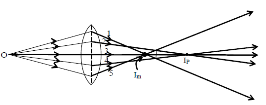
Spherical Aberration:
Face of the lens that is exposed to light is called aperture. If aperture is large, light rays incident at different portions (zones) of the aperture, refract diversely. Rays close to principal axis are called paraxial rays. These rays converge at a farther point (IP) from the lens after refraction than the marginal or peripheral rays, falling near the edges of the lens. The marginal rays converge at a closer point (Im) from the lens.
Thus the image extends between point Im and IP, and a sharp point image is not possible for a point object. This defect is called spherical aberration. The distance between Im and IP is the measure of the spherical aberration, and is called the longitudinal (axial) spherical aberration.
The aperture of a lens can be mentally divided as annular rings (zones) of different radii. It has been shown that the longitudinal spherical aberration is proportional to the square of the radius of the zone. Also, spherical aberration increases as the square of the deviation (distance of the object ray above the axis of the lens) of the object ray from the axis of the lens. Spherical aberration of a converging lens (convex) is considered positive and of a diverging lens (concave) negative.
Methods to minimize spherical aberration:
1. By using stops: Spherical aberration can be reduced by decreasing the aperture of the lens. This can be done by using a stop (diaphragm) in front of the lens. This method reduces the brightness and details of the image. Alternatively the central portion of the lens is obscured by a stop allowing only the peripheral rays to form the image. This improves the definition of the image.
2. Bending of a lens: The shape of the lens is modified to minimize the spherical aberration. This process is called bending the lens. A quantity known as shape factor of a lens is defined as where R1 and R2 are the radii of curvature of the lens. This factor measures the symmetry of the shape of the lens. The bending of a lens is to find that shape of the lens for which spherical aberration is minimum. To determine the proper shape of the lens of material of index of refraction 1.5, we have to choose the values of R1 and R2 in such a way that the ration or the shape factor so that longitudinal spherical abervation is a minimum.
3. By using palno-convex lenses: It is said that spherical aberration is proportional to the square of the deviation of the rays produced at the surface. To minimize the deviation at the surfaces of the lens a plano-convex lens is used and the rays are allowed to fall on the convex side. This orientation of the lens minimizes the spherical aberration.
By the use of two plano-convex lenses separated by a finite distance (x) equal to the difference of their focal lengths i.e., x = (f1 ~ f2) we can minimize spherical aberration.
4. Suitable combination of concave and convex lenses: Suitable combination of concave and convex lenses minimizes spherical aberration, because a concave lens produces a negative spherical aberration and a convex lens a positive spherical aberration.
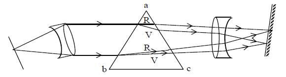
Chromatic aberration:
A lens may be thought of as a pile of prisms placed one over the other as shown in fig. The angles of these prism pieces, which determine the deviation of rays, are different. This is the reason why light rays incident above and below the principal axis of a convex lens bend towards the axis after refraction and converge to a point on it. In the case of a concave lens, the rays, after refraction bend away from the axis and appear to diverge from a point on it. If the rays passing through the lens are white rays, along with refraction they also split up into the constituent seven colours. This phenomenon is known as dispersion.
Chromatic aberration is due to the variation of the refractive index of the lens with the colour. The refractive index μ and hence the focal length f, are dependent on the wave length of the incident light. Since the magnification and the position of the image by a lens depend on the focal length, the size and position of the images varies with the color.
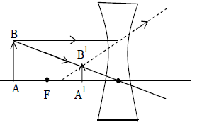
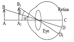
Violet and red rays are brought to focus at different point with different magnification. The deviation of violet rays is maximum and they meet (at point B1) nearer to the lens. The deviation of red rays is minimum and they meet at a farther point B2 from the lens. The rays of other colours meet at different point between B1 and B2. Thus the image produced by a single lens appear to be blurred and coloured when white light is used. This defect in formation of the image is known as chromatic aberration.
X = Longitudinal chromatic aberration (B1, B2); y = Lateral chromatic aberration (A1, A2) AB – object. L – Lens (Convex). O-Optic Centre, 1 = Voilet Image, 2 = Red Image. Chromatic aberration: Chromatic aberration is classified as (i) longitudinal (axial) chromatic aberration and (ii) lateral (transverse) chromatic aberration.
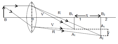
i) Longitudinal chromatic aberration: The horizontal distance (along the axis) between the red image and the violet image (i.e., B1B2 = x) is the measure of longitudinal or axial chromatic aberration.
ii) Lateral chromatic aberration: The difference between the size of the image formed by red rays and that formed by violet rays (i.e., A2 – A1 = y) is the measure of lateral or transverse chromatic aberration.
Elimination of chromatic aberration:
1) Archromatic combination of two lenses in contact: A concave lens produces chromatic aberration in the opposite sense as compared to a convex lens. Therefore we can combine a convex lens with a suitable concave lens to eliminate chromatic aberration.
A combination of a convex and a concave lens made of different materials cemented together suitably to eliminate chromatic aberration is called an achromatic doublet. A widely used achromatic doublet is designed with convex lens of low focal length made of crown glass and a concave lens of greater focal length made of flint glass cemented with Canada balsam. The combination acts as a convex lens.
2) Achromatic combination of two lenses separated by a distance:
Two thin lenses of the same material arranged on a common axis separated by distance equal to the average of their focal lengths minimizes chromatic aberration.
27. EYEPIECES
Prototype optical instruments such as telescopes and microscopes had one object lens and one eye lens only. Single lens forms images with chromatic and spherical aberrations. So, in designing telescopes and microscopes for practical purposes, combination of lenses are used for both objective and eye lenses to minimize chromatic and spherical aberrations. A combination of lenses used as an eye lens is known as eyepiece.
An eye piece mainly consists of a field lens and an eye lens. Field lens and eye lens are arranged in such a way that spherical and chromatic aberrations are considerably reduced or eliminated.
Field lens increases the field of view and the eye lens acts as a magnifier.
We consider two eyepieces viz Ramsden’s eyepiece and Huygens’ eyepiece.
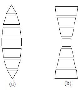
Construction of Ramsden’s eyepiece:
This eye piece consists of two plano-convex lenses of equal focal length (f), separated by a distance (d) equal to 2f/3. The lenses are arranged on a common axis so that their convex surfaces face each other. This type of orientation of the lenses minimizes spherical aberration as the refracting surfaces of the lenses share deviation equally. The eyepiece is placed beyond the image (I) formed by the objective.
The equivalent focal length of the combination is calculated by the relation.
Where F is the equivalent focal length (focal length of eye piece) f1 and f2 are focal lengths of the field lens and eye lens respectively. In this eye piece f1 = f2 = and d = 2f/3; and from the equation for F, we have
Since the focal length of the eyepiece is 3f/4, the image (I) formed by the objective must be at a distance of f/3 in front of field lens (L1). This image serves as an object for the field lens and its image I1 (virtual) is formed at a distance of f/3 in front of field lens. I1 lies in the focal plane of the eye lens (L2) and it acts as an object for the eye lens which forms its image at infinity. In this eyepiece, the cross-wires are placed in the position of the real image I, formed by the objective i.e., at a distance of f/4 in front of the field lens. Due to this reason the eyepiece is referred to as positive eyepiece. A fine scale may be placed at this point to take measurement pertaining to the image.
Advantages:
i) Since cross wires are provided, this eyepiece is used for taking measurements. As the scale and the image are magnified proportionally, measurements would be trust worthy.
ii) As convex surfaces are facing each other, the spherical aberration is minimum because the total deviation is shared by the four refracting surfaces.
Demerits:
This eye piece cannot totally eliminate chromatic aberration because the distance ‘d’ (=2f/3) between the lenses is not equal to the average of their focal lengths (f). If distance between the lenses were ‘f’, chromatic aberration would totally be eliminated but any dust particles on the field lens also be magnified and seen in sharp focus along with the image which is an undesirable feature.
Construction of Huygen’s eyepiece:
This eyepiece consists of two plano-convex lenses of same glass material. The focal length ratio of field and eye lens varies from 1.5 to 3. However we consider the ratio 3 : 1, that is focal length of the field lens is 3f, and that of eye lens is f. The two lenses are separated by a distance d equal to 2f on a common axis and arranged with their convex faces toward the objective.
The focal length (F) of equivalent lens is found by the formula.
Where f1 = 3f, f2 = f, and d = 2f, and
This eye piece is adjusted such that the image (I0) formed by the objective lens must be at a distance of 3f/2 beyond the field lens. This will serve as a virtual object for field lens and its image is formed at I1, I1 lies in the focal plane of the eye lens and acts as an object for it which forms the final image at infinity. This eyepiece satisfies the conditions of minimum spherical and chromatic aberrations.
Since the image formed by the objective (I0) lies behind the field lens this eye piece is referred to as a negative eyepiece. Cross wires may be placed in the position of the real image I1. i.e., midway between the field lens and eye lens.
i) Chromatic aberration is totally eliminated because the distance between the lenses is equal to the average of the focal lengths of the field lens and the eye lens.
ii) Spherical aberration is also minimum because the distance between the field lens and eye lens is equal to the difference of their focal lengths. e., d = (3f – f) = 2f.
Demerits:
1. Field of view of Huygens’ eyepiece is lower than that of Ramsden’s eyepiece.
2. The measurements with Huygens’ eyepiece are not reliable because image magnification and scale magnification (scale fixed to the cross –wires) are not proportional. The image is magnified by both lenses where as the scale is magnified by a single lens.
Comparison between Ramsden’s and Huygen’s eye pieces
| Ramsden’s eye piece | Huygens’ eye piece | ||
| 1) | The image formed by the objective is real and lies in front of the field lens at a distance f/4 from it. | 1) | The image formed by the objective is real and lies midway between the field lens and eye lens. |
| 2) | Measurements are reliable as cross wires, scale and final image are magnified in equal proportions. | 2) | As the cross wires, scale and the final image are magnified disproportionately, measurements are not reliable. |
| 3) | This is a +ve eyepiece | 3) | This is a -ve eyepiece |
| 4) | Condition for minimum spherical aberration is not satisfied (d ≠ f=2 ~ f1) | 4) | Condition for minimum spherical aberration is satisfied d = f2 ~ f1 = 3f – f = 2f |
| 5) | Condition for achromatism is not satisfied completely | 5) | Condition for achromatism is satisfied |
| 6) | The cross wires are placed outside the eyepiece. It is easier process. | 6) | If the cross wires were to be used, they are to be placed mid-way between the lenses. This is difficult process. Usually Huygen’s eye pieces are available without cross wires. |
Illustration 23: A hypermetropic person whose near point is at 100 cm wants in read a book at 25 cm. Find the nature and power of the lens needed.
Sol. Here, u = – 25cm v = – 100 cm, f = ?
As
The lens must be converging.
28. SPECTRUM
Origin of Spectra: The ordered arrangement of radiations according to wave lengths or frequencies is called spectrum when an external energy is supplied to the atom, the electron absorbs this energy and goes to the higher orbit. Now the atom is to be in the excited state. The excited atom returns to its ground state after 108 s by emitting radiation or radiations of certain wave length.
The energy of the radiation emitted = difference in energy of higher orbit and lower orbit.
which is the wavelength of the emitted radiation
The ordered arrangements of radiations according to wavelengths or frequencies is called Spectrum. Spectrum can be divided in two parts Emission spectrum and absorption spectrum.
1) Emission spectrum: When light emitted by a self luminous object is dispersed by a prism to get the spectrum, the spectrum is called emission spectra. Continuous emission spectrum:
i) It consists of continuously varying wavelengths in a definite wavelengths range.
ii) It is produced by solids, liquids and highly compressed gases heated to high temperature.
iii) e.g., Light from the sun, filament of incandescent bulb, candle flame etc.
Line emission spectrum:
i) It consists of distinct bright lines.
ii) It is produced by excited source in atomic state.
iii) e.g., Spectrum of excited helium, mercury vapours sodium vapours of atomic hydrogen.
Band emission spectrum:
i) It consist of district bright bands.
ii) it is produced by an excited source in molecular state.
iii) e.g., Spectra of molecular H2, CO, NH3 etc.
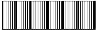
2) Absorption spectrum: When while light passes through a semi transparent solid, or liquid or gas, it’s spectrum contains certain dark lines or bands, such spectrum in called absorption spectrum (of the substance through which light is passed)
i) Substances in atomic state produces line absorption spectra. Polyatomic substances such as H2,CO2 and KMnO4 produces band absorption spectrum.
ii) Absorption spectra of sodium vapour have two (yellow lines) wavelengths D1 (5890 Å)
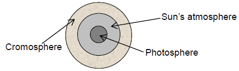
3) Fraunhoffer’s lines: The central part (photosphere) of the sun is very hot and emits all possible wavelengths of the visible light. However, the outer part (chromosphere) consists of vapours of different elements. When the light emitted from the photosphere passes through the chromosphere, certain wavelengths are absorbed. Hence, in the spectrum of sunlight a large number of dark lines are seen called Fraunhoffer lines.
i) The prominent lines in the yellow part of the visible spectrum were labelled as D-lines, those in blue part as F-lines and in red part as C-line.
ii) From the study of Fraunhoffer’s lines the presence of various elements in the sun’s atmosphere can be identified e.g., abundance of hydrogen and helium.
iii) In the event of solar eclipse, dark lines become bright. This is because of the reason that the presence of an opaque obstacle in between sun and earth cuts the light off from the central region (photo-sphere), while light from corner portion (cromosphere) is still being received. The bright lines appear exactly at the place where dark lines were present.
4) Spectrometer: A spectrometer is used for obtaining pure spectrum of a source in laboratory and calculation of μ of material of prism and μ of a transparent liquid.
It consists of three parts: Collimator which provides a parallel beam of light; Prism Table for holding the prism and Telescope for observing the spectrum and making measurements on it.
The telescope is first set for parallel rays and then collimator is set for parallel rays. When prism is set in minimum deviation position, the spectrum seen is pure spectrum. Angle of prism (A) and angle of minimum deviation (m) are measured and μ of material of prism is calculated using prism formula. For μ of a transparent liquid, we take a hollow prism with thin glass sides. Fill it with the liquid and measure (m) and A of liquid prism, μ of liquid is calculated using prism formula.
5) Direct vision spectroscope: It is an instrument used to observe pure spectrum. It produces dispersion without deviation with the help of n crown prisms and (n – 1) flint prism alternately arranged in a tabular structure.
For no deviation
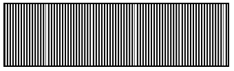
29. PURE AND IMPURE SPECTRUM
Pure Spectrum: The coloured pattern obtained on the screen after dispersion of light is called spectrum. If there is no overlapping of colours in the spectrum. It is called a pure spectrum.
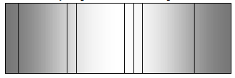
Impure spectrum: If various colours in the spectrum mix with one another, it is called an impure spectrum. To obtain the pure spectrum the following conditions must be fulfilled.
i) There should be a fine slit to give a fine beam of light.
ii) An achromatic converging lens should be placed in front of the slit to render the incident beam of light parallel. This can be achieved by placing, the slit at the focal plane of the lens.
iii) The prism should be placed in the minimum deviation position with its refracting edge parallel to the slit.
iv) Another achromatic converging lens is placed to focus the emergent rays of different colours at different positions.
The arrangement for the formation of pure spectrum in the laboratory is shown in fig.
Uses of spectrometer:
i) It is used to measure the refractive index of the material of a prism.
ii) It is used to measure the refractive index of the transparent liquid.
iii) It is used to obtain and analyse the pure spectrum.
OPTICAL INSTRUMENTS
The devices which work on the principle of refraction, reflection or recti-linear propagation of light etc are called optical instruments.
Human eye can also be treated as a natural optical camera.
30. HUMAN EYE
i) It has convex eye lens which forms real, inverted and diminished image at the retina of eye
ii) The ability of eye to adjust the convexity of its lens with a view to focusing the object at different distances on the retina, is called as its power of accommodation.
iii) For a normal eye, (a) near point or least distance of distinct vision (D) = 25 cm and (b) far point = ∞.
iv) If time interval between two light pulses is less than s human eye can not differentiate them. This is known as persistence of vision.
v) In twilight, eye is most sensitive to bluish-green region. In broad day light, eye is most sensitive to greenish-yellow region.
vi) While testing your eye through reading chart, doctor finds it to 6/12, it implies that you can read a letter from 6m which the normal eye can read from 12 m. Thus, 6/6 means normal eye sight.
31. COMMON DEFECTS OF VISION
The common defects of vision are as follows:
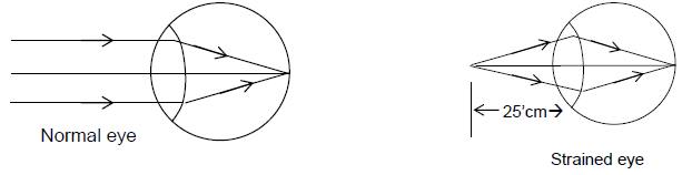
i) Myopia or short sightedness: The patient can see the near object but not the far object. The image of distant object formed before the retina. The defect can be remedied by using a concave lens.
Cause of myopia:
i) Due to decrease in the focal length of eye lens or
ii) Due to increase in the size of eye ball.
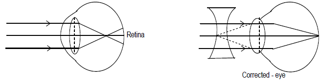
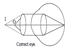
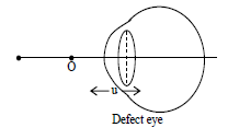
ii) Hyperopia or farsightedness: The patient can see far objects clearly but not the near objects. The image of near object is formed behind the retina. The retina can remedied by using a convex lens.
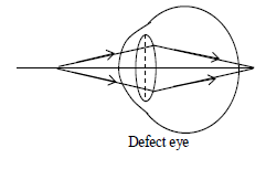
The defect can remedied by using a convex lens (In order to calculate the focal length of the correcting lens.
u =25cm
v = -(near point at defect eye)
iii) Presbyopia: In prebyopia, the patient can neither see the near objects nor the far object clearly. This is due to decrease in the compressibility of the eye lens with advancing age. This leads to a gradual decrease in the power of accommodation. This is remedial either by using two separate lenses or by using single spectacle having bifocal lenses.
iv) Astigmatism: In this defect eye cannot see objects in two orthogonal (perpendicular directions clearly This defect is remedial by using cylindrical or spherocylindrical lenses.
Visual angle: The size of the image on the retina is roughly proportional to the angle subtended by the object on the eye. This angle is known as the visual angle. Optical instruments are used to increase this angle artificially in order to improve the clarity. The greater is the visual angle the larger is the apparent size of the object.
Magnifying power: Magnifying power is the factor by which the image on the retina can be enlarged by using the microscope or telescope. For a microscope and for a telescope the definition of M is slighting different.
For a microscope:
For a telescope:
Note: That M is different from linear magnification which is the ratio it height of image to that of object, while m is the ratio of apparent increase in size of image seen by the eye.
Unit of M is X, we write an angular magnification of 10 as 10X. To view an object with naked eyes, the object must be placed between D and infinity. The maximum angle is subtended when it is placed at D say this angle is θ0, then .
Illustration 24: A farsighted woman has a near point of 1.5m. Calculate the focal length of the lenses for her eye glasses so that she can read a book at 25 cm.
Sol: Here u = -25 cm, v = – 1.5 cm = -150 cm
By lens formula
f = + 30 cm
Illustration 25: The far point of a short-sighted woman is 75 cm from the eye. What focal length lens should the woman use in order to focus on a very distant object (u = ∞)?
Sol. Here the far point for a normal eye is at infinity.
∴ u = -∞, v = -75, f = ?
Now,
f = -75 cm.
32. MICROSCOPES
A microscope is an instrument which forms on enlarged image at a small object placed close to the eye. There two types of microscope.
i) Simple microscope or magnifying glass ii) Compound Microscope
SIMPLE MICROSCOPE
A simple microscope is based upon the fact if an object is placed between the optical centre and focus of a convex lens, it produces a virtual and large image of the object on the same side of the lens.
It consists of a convex lens of small focal length. The image formed is very bright and sharp because object is held very close to the lens we discuss two situations.
When image formed at the near point (distinct vision): This situation is shown in figure. The object AB is placed within the focus of the lens. A virtual erect w.r.t. object and magnified image A|B| formed behind the object. The lens is adjusted so that the image is at the near point.
Magnifying power M = , Where B = angel subtended at the eye by the image at the near point, α = angle subtended at the unaided eye by the object at the near point.
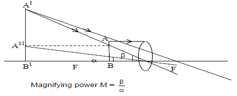
since α and β are very small
i) In this case angular magnification is equal to the linear magnification
……….. (1)
since v = -D, u = -u (singn convention)
from lens formula
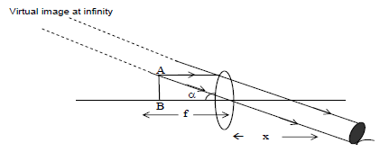
ii) When image is formed at infinity (normal vision)
To see the image with relaxed eye, the image must be formed at infinity. The microscope is in normal adjustment when the image is formed at infinity i.e. v = ∞ and u = -u
from lens formula
from equation (1)
Note:
i) To increase the magnification of a simple microscope, a lens of shorter focal length should be used.
ii) If the eye is kept at a distance x from the lens. Then
iii) The magnification of a simple microscope is less than 20.
iv) Its magnifying power decreases when immersed, in water (due to increase of focal length)
COMPOUND MICROSCOPE
A compound microscope is used to see small objects which cannot even be seen by the simple microscope. It consists of two converging lenses arranged coaxially. The one facing the object is called objective and one close to eye is called eye piece. The objective has a smaller aperture and smaller focal length than those of the eye piece. The separation between the objective and the piece is called length of the microscope L and can be varied by screws.
The object is placed beyond first focus of objective, so that an inverted and real image (intermediate image) is formed by the objective. This intermediate image acts as an object for the eye piece and lies between first focus and pole of eye piece. The final magnified virtual image is formed by the eye piece.
Magnifying power of compound microscope:
It is ratio of the angle subtended by the final image of the eye to the angle subtended by the object at the eye when both are at a distance at least distance of distinct vision.
(α, β are very small)
Case i) When image is formed at near point
Value of Me: The focal length of eye piece is fe and it forms the final image A||B|| of the intermediate image A|B| at the near point.
Value of M0: The distance of the object AB from the objective lens is u0. The distance of the image A1B1 formed by the objective is V0 from if
Length of microscope will be L = v0 + ue
Since focal length of the objective lens is very small, u0 v0
[Note that final image formed is inverted w.r.t. the object so that M is negative]
ii) When image is formed at infinity (normal adjustment): M = Me x Mo
As shown earlier
when the image is formed at infinity, as for a simple microscope
33. TELESCOPE
Telescope is an optical instrument to clearly observe the distant objects.
Types of telescopes: Telescopes are basically of two types i.e. refracting and reflecting The refracting type telescopes are
i) Astronomical telescope ii) Terrestrial telescope iii) Galilean telescope
i) Astronomical telescope:
This telescope is used to observe heavenly objects like moon, distant starts etc. The image formed by this telescope is virtual and inverted. It consists of two converging lenses placed coaxially. The focal length f0 of objective lens is greater than focal length (fe) of eye piece. The eye piece tube can slide within the objective tube, so that the separation between the objective and the eye piece may be varied.
The objective lens produces a real image of the object being viewed. This (intermediate) image acts as an object for the eye piece lens, which, behaving as a magnifying glass, produces a virtual image of it.
In this case, length of telescope
Illustration 26: A person uses + 1.5D glasses to have normal vision from 25 cm onwards. He uses a 20D lens as a simple microscope to see an object. Calculate the maximum magnifying power, if he used the microscope (a) together with his glasses (b) without the glasses.
Sol. Here, P1 = 1.5 D : d = 25cm,
P2 = 20 D
(a) With glasses on
(b) Without glasses,
Focal length of glasses,
u = – 25cm, v = ?
As v = – 40 cm
Illustration 27: A compound microscope has an objective of focal length 1 cm and an eye piece of focal length 2.5 cm. An object has to be placed at a distance of 1.2cm away from the objective normal adjustment. Find the angular magnification and length of the microscope tube.
Sol. Here, f0 = 1cm, fe = 2.5cm
As
v = 1.2/0.2 = 6cm
As
Terrestrial Telescope:
Terrestrial telescope is used to see the objects on the earth, so the image produced should be erect. It consists of three converging lenses namely objective, eyepiece and field lens.
In normal adjustment:
Length of telescope = fo + 4fa + fe ,
Magnifying power =
If the final image is formed at the least distance of distinct visions then magnifying power =
Galilean telescope:
The main disadvantage of the terrestrial telescope is that it is very long. The Galilean telescope does not have this disadvantage. In such telescope a concave lens is used as an eye piece which revolves the field of view. This telescope suffers from loss of brightness.
It has same expressions for M.P. as in the case of astronomical telescope. The separation between the objective and eye piece is given by L = fo – ue or L = fo – fe
Characteristics of a telescope:
A good telescope should have high resolving power, large light gathering power and magnifying power.
a) Resolving power: Resolving power of a telescope is reciprocal of the least angular separation between two far off objects whose images are just separately seen through the telescope i.e. resolving power is given by
when dα = least angular separation between two distant object (known as limit of resolution)
D = diameter of the objective lens.
λ = Wave length of light used.
Light gathering power: The light gathering power (or brightness) of a telescope is directly proportional to the area of the objective lens πr2
where D is the diameter of the objective
c) Brightness ratio: The brightness ratio of a telescope is defined s the ratio of the light gathered by the telescope to the light gathered by the unaided eye from the distant objects.
D = diameter of the objective lens of the telescope.
d = diameter of the eye lens.
∴ light gathered by the objective of the lens
∴ Light gathered by the unaided eye
Brightness ratio =
Illustration 28: Calculate the resolving power of a microscope with cone angle of light falling on the objective equal to 300, Take λ = 600 nm and μ for air = 1.
Solution. Here, R.P. = =
Illustration 29: An astronomical telescope has a magnifying power of 10. In normal adjustment, distance between the objective and eye piece is 22cm. Calculate focal length of objective lens.
Solution. Here, m = – 10, L = 22 cm, f0 = ?
As
As L = f0 + fe
Illustration 30: A telescope has an objective of focal length 50cm and eye piece of focal length 5 cm. The least distance of distinct vision is 25 cm. The telescope is focused for distinct vision on a scale 200 cm away from the objective. Calculate (i) the separation between objective and eye piece (ii) the magnification produced.
Solution. Here, f0 = 50cm, fe = 5cm
d = 25 cm, v0 = – 200 cm
m = ? L = ?
As
Exercise 4:
(i) If a telescope is inverted, will it be able to work as a microscope?
(ii) What is the distance between objective and eye lens of telescope in normal adjustment?
(iii) A short sighted person cannot see clearly beyond 2m. Calculate power of the lens required to correct his eye to normal vision.
(iv) A compound microscope has a magnification of 30. The focal length of the eye piece is 5 cm. Assuming that final image is formed at the least distance of distinct vision (25 cm), calculate the magnification produced by the objective.
(v) An astronomical telescope consists of two thin lenses set 36 cm apart, and has a normal magnifying power 8. Calculate the focal lengths of lenses.
Answer to Exercises
Exercise 1:
(i) 450
(ii) (a) 2 ⨯108 m/s; 3.3 ⨯ 10-7 m (b) 3 ⨯ 108 m/s; 5 ⨯ 10–7 m
(iii) 0.96 m
(iv) 1.635 times
Exercise 2:
(i) 2.5 cm (ii) – 30 cm (iii) 30 cm, – 20 cm (iv) 2.5 D (v) 10D, 10 cm
Exercise 3:
(i) 1.64 (ii) 230 22′ (iii) 1.532, 500 (iv) 406′
Exercise 4:
(i) (No, it will not) (ii) (x = (f0 + fe). (iii) – 0.5 D (iv) 532cm ,4cm
FORMULAE AND CONCEPTS IN A GLANCE
1)
2) When light travels from medium a to medium b
3)
4) Lateral shift =
5)
6)
7) Displacement of image = x – y.
8) For TIR, light must travel from denser to rarer medium. Angle of incidence (i) in denser medium must be greater than critical angel (C) for the pair of media in contact.
9)
10) Lens Maker’s formula is ,
where
11) Lens equation :
12) Magnification of lens,
13) Power of lens
REFRACTION THROUGH A PRISM
1) In refraction through a prism
(i)
(ii) r1 + r2 = A
(iii) when
2)
3) Mean deviation, , when A is small.
DISPERSION THROUGH A PRISM
1) Angular dispersion =
When angle of prism A is small
2) Mean deviation,
3) Mean refractive index,
4) Dispersive power
5) For deviation without dispersion, condition is
Net deviation =
6) For dispersion without deviation, condition is
Or
Net dispersion =
THE DEFECTS OF VISION
1) Myopin or short sightedness
For observing distant object, a concave lens of focal length f = – x is to be used, where x is distance of far point of defective eye.
2) Hypermetropia or Long sightedness
For observing near objects, a convex lens of focal length f is to be used.
Where
Here, u = d = least distance of distinct vision of normal eye v = – x = distance of near point of defective eye.
SIMPLE AND COMPOUND MICROSCOPE
1) Magnifying power of a simple microscope,
2) Magnifying power of a compound microscope,
For a normal eye, d = 25 cm
1) Astronomical Telescope
a) in normal adjustment
b) When final image is at the least distance of distinct vision,
c) Distance between the two lenses in normal adjustment x = f0 + fe
2) Terrestrial telescope
Formulae for magnifying power are same as given above. Distance between objective lens and eye lens in normal adjustment.
Where f is focal length of erecting lens.
3) Reflecting type telescope
Where f0 is focal length of objective mirror.
SOLVED PROBLEMS-1
Prob 1. In a tank, a 4 cm thick layer of water floats on a 6 cm thick layer of an organic liquid (μ = 1.48). Viewing at normal incidence, how far below the water surface does the bottom of tank appear to be?
Sol.
Prob 2. A ray of light incident at an angle of 500 is refracted through a prism in the minimum deviation position. The angle of the prism is 600. Find the angle of minimum deviation and refractive index ‘μ’ of the prism.
Sol. Here, A = 600 and i = 500. So, in the position of minimum deviation.
and,
Prob 3. A ray of light passing through a prism having suffers minimum deviation. It is found that the angle of incidence is double the angle of refraction within the prism. What is the angle of prism?
Sol. In case of minimum deviation, fm = (2i – A) and r = A/2
According to given problem, i = 2r = A
So, m = 2A – A = A
Then,
or,
or,
Prob 4. White light is passed through a prism of angle 50. If the refractive indices for red and blue colours are 1.641 and 1.659 respectively, calculate the angle of dispersion between them.
Sol. As for small angle of prism
and,
Prob 5. What is the refractive index of material of a plane convex lens, if the radius of curvature of the convex surface is 10cm and focal length of the lens is 30 cm?
Sol. According to lens – maker formula,
Here, f = 30cm, R1 = 10cm and R2 = ∞
so, or,
Prob 6. A man who wears glasses of power 3 dioptre must hold a news paper at least 25cm away to see the print clearly. How far away would the news paper have to be if he took off glasses and still wanted clear vision.
sol. As here, u = – 0.25 and
Then from lens formula,
or
or,
or v = – 1m
i.e., the lens shifts the object from 25cm to for clear vision i.e., his near point is 1m. So in absence of glasses, he must held the newspaper at a distance of 1m away from his eyes for clear vision.
Prob 7. In a compound microscope, the object is 1cm from the objective lens. The lens are 30cm apart and the intermediate image is 5cm from the eye piece. What magnification is produced?
Sol. As the lenses are 30cm apart and intermediate image is formed 5cm in front of eye lens.
ue = 5cm and V = L – ue = 30 – 5= 25 cm
Now, in case of compound microscope.
Here, u = 1cm and D = 25cm
So,
Negative sign implies that the final image is inverted.
Prob 8. Why does a convex lens of glass μ = 1.5 behave as a diverging lens when immersed in carbon disulphide of μ = 1.65?
Sol. Here,
From lens maker formula,
Then, f becomes negative.
Therefore, the lens behaves as a diverging lens.
Prob 9. The focal length of an equiconvex lens placed in air is equal to radius of curvature of either face. Is it true?
Sol. Yes, f = R only when μ = 1.5
From lens maker formula,
But, if μ ≠ 1.5, then f ≠ R.
Prob 10. Within a glass slab, a double convex air bubble informed. How would the air bubble behave?
Sol. The air bubble would behave as diverging lens, because μ of air is less than μ of glass. However the geometrical shape of the air bubble shall resemble a double convex lens.
SOLVED PROBLEMS-2
Prob 1. Three plane mirrors are mutually perpendicular. The maximum number of images which can be formed is
(A) 7 (B) 3 (C) 9 (D) 6
Sol. (A) Hence,
4 -3 = 1 images will be formed by two mirrors held perpendicular. In third mirror reflected rays of these images will reach and form 3 mirror images and one direct image for the object making total of 7.
Prob 2. A cube of glass has an air bubble. When seen from one face it appears 12cm and when seen from opposite face it appears 6 cm. The size of the cube is
(A) 18 cm (B) 27 cm (C) 9 cm (D) 21 cm
Sol. (B) Read depth = μ (d1 + d2) = 1.5 (12 + 6) = 27 cm.
Prob 3. A candle has flame 1 inch high. It is placed in front of a steel ball of radius 2cm. The height of the image is (if the candle is 10 cm away)
(A) 1 inch (B) 1/10 inch (C) 1/11 inch (D) 1/9 inch
Sol. (C) Here, focal length = f = = 1 cm using mirror formula,
Now,
Prob 4. Two 2cm long plane mirrors are kept 10cm apart as shown in figure. A ray is incident at is 450. The number of reflections the ray will suffer
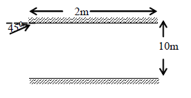
(A) 19 (B) 20 (C) 21 (D) 22
Sol. (A)
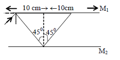
Figure makes clear that in one reflection the beam covers a distance 20cm an one mirror. Therefore 10 reflection will occur from mirror M1 and a from M2 making total 19.
Prob 5. Two thin lenses have focal lengths 20cm and – 40cm. The focal length of combination in contact is
(A) 20 cm (B) 40 cm (C) – 20 cm (D) – 40 cm
Sol. (B) We know that,
=
Then, f = 40 cm
Prob 6. A small object of length l is placed is front of a lens of focal length f axially. The rise of its image is
(A) (B) (C) (D)
Sol. (A) We know that, lens formula,
or or
size of image =
Prob 7. The magnifying power of a telescope (Astronomical) is 8 and the distances between two lenses is 54cm. The focal length of objective and eye piece are respectively (in cm)
(A) 6, 48 (B) 48, 6 (C) 8, 64 (D) 64, 8
Sol. (A) Here, fo + fe = 54 and
Then, 9fe = 54 or fe = 6cm, fo = 48 cm
Prob 8. A convex lens forms a real image of an object for its two different positions on the screen. If the height of images in two cases are 8 cm and 2cm then the height of the object is
(A) 8 cm (B) 4 cm (C) 2 cm (D) none of these
Sol. (B)
Prob 9. A thin prism P1 of angle 40 made of μ = 1.54 is combined with a prism P2 of μ = 1.72 to produce dispersion without derivation. The angle of prism P2 is
(A) 5.530 (B) 40 (C) 30 (D) 2.60
Sol. (C) (μ1 – 1) α1 = (μ2 – 2) α2
or, (1.54 – 1) X 40 = (1.72 – 1) α2 or, α2 = 30
Prob 10. A planoconvex lens has aperture 6cm and thickness 3 mm. Its focal length is
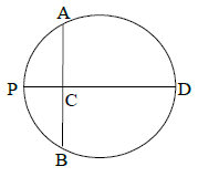
(A) 15 cm (B) 30 cm (C) 20 cm (D) 25 cm
Sol. (A) Here, AC ⨯ BC = PC ⨯ CD
or, 3 ⨯ 3 = t (2R – t) ( AB = 6 cm)
or, or 2R = 30.3cm
(t = PC = 0.3cm)
or,