


MAGNETISM AND MATTER
1. BAR MAGNET AND TERMS RELATED TO BAR MAGNET
The molecular theory of magnetism was given by Weber and modified later by Ewing. According to this theory.
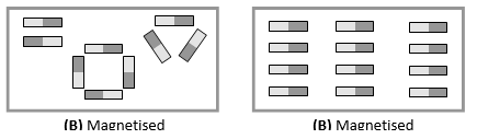
Every molecule of a substance is a complete magnet in itself. However, in an magnetic substance the molecular magnets are randomly oriented to give net zero magnetic moment. On magnetising, the molecular magnets are realigned in a specific direction leading to a net magnetic moment.
1. BAR MAGNET
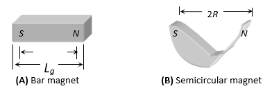
A bar magnet consist of two equal and opposite magnetic pole separated by a small distance. Poles are not exactly at the ends. The shortest distance between two poles is called effective length (Le) and is less than its geometric length (Lg). for bar magnet Le = 2l and Le = (5/6) Lg. for semi circular magnet and
2. PROPERTIES AND TERMS RELATED TO A BAR MAGNET
I. DIRECTIVE PROPERTIES
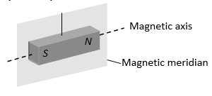
When a magnet suspended freely it stays in the earth’s N-S direction (in magnetic meridian).
II. MONOPOLE CONCEPT
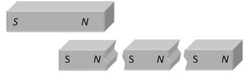
If a magnet is Broken into number of pieces, each piece becomes a magnet. This in turn implies that monopoles do not exist. (i.e., ultimate individual unit of magnetism in any magnet is called dipole).
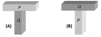
III. MAGNETISM TEST
For two rods as shown, if both the rods attract in figure (A) and doesn’t attract in figure (B) then, Q is a magnetic and P is simple iron rod. Repulsion is sure test of magnetism.
IV. POLE STRENGTH (M)
The strength of a magnetic pole to attract magnetic materials towards itself is known as pole strength.
(i) It is a scalar quantity.
(ii) Pole strength of N and S pole of a magnet is conventionally represented by +m and –m respectively.
(iii) It’s SI unit is amp × m or N/Tesla and dimensions are [LA].
(iv) Pole strength of the magnet depends on the nature of material of magnet and area of cross section. It doesn’t depends upon length.

V. MAGNETIC MOMENT OR MAGNETIC DIPOLE MOMENT
It represents the strength of magnet. Mathematically it is defined as the product of the strength of either pole and effective length. i.e.
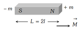
(i) It is a vector quantity directed from south to north.
(ii) It’s S.I. unit amp×m2 or N-m / Tesla and dimensions [AL2]
VI. CUTTING OF A RECTANGULAR BAR MAGNET
Suppose we have a rectangular bar magnet having length, breadth and mass are L, b and w respectively if it is cut in n equal parts along the length as well as perpendicular to the length simultaneously as shown in the figure then
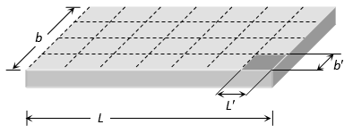
Length of each part , breadth of each part , Mass of each part , pole strength of each part , Magnetic moment of each part
If initially moment of inertia of bar magnet about the axes passing from centre and perpendicular to its length is then moment of inertia of each part
VII. CUTTING OF A THIN BAR MAGNET
For thin magnet b = 0 so
2. MAGNETISM, CONCEPTS & TERMS RELATED TO IT
1. MAGNETIC FIELD AND MAGNETIC LINES OF FORCE
Space around a magnetic pole or magnet or current carrying wire within which it’s effect can be experienced is defined as magnetic field. Magnetic field can be represented with the help of a set of lines or curves called magnetic lines of force.
MAGNETIC FLUX () AND FLUX DENSITY (B)
(i) The number of magnetic lines of force passing normally through a surface is defined as magnetic flux (). It’s S.I. unit is weber (wb) and CGS unit is Maxwell.
Remeber 1 wb = 108 Maxwell.
(ii) When a piece of a magnetic substance is placed in an external magnetic field the substance becomes magnetised. The number of magnetic lines of induction inside a magnetised substance crossing unit area normal to their direction is called magnetic induction or magnetic flux density . It is a vector quantity.

It’s SI unit is Tesla which is equal to
and CGS unit is Gauss. Remember 1 Tesla = 104 Gauss.
3. MAGNETIC PERMEABILITY
It is the ability of a material to permit the passage of magnetic lines of force through it i.e. the degree or extent to which magnetic field can penetrate or permeate a material is called relative magnetic permeability of the material. It is represented by r.
Relative magnetic permeability of a material is defined as the ratio of the number of magnetic field lines per unit area (i.e. flux density B) in that material to the number of magnetic field lines per unit area that would be present, if the medium were replaced by vacuum. (i.e. flux density Bo).
i.e.,
r has no dimensions. Its value for vacuum is one.
Relative magnetic permeability of a material may also be defined as the ratio of magnetic permeability of the material () and magnetic permeability of free space (0)
We know that 0 = 4 × 10⁻⁷ weber/amp-metre (Wb A-1 m-1) or henry/metre (Hm-1)
SI units of permeability () are Hm-1 = Wb A-1 m-1 (Tm2) A-1 m-1 = T mA-1.
4. INTENSITY OF MAGNETISING FIELD (MAGNETISING FIELD)
The degree to which a magnetic field can magnetise a material is represented in terms of magnetizing force or magnetising intensity ()
Let us consider a toroidal solenoid with n turns per unit length carrying a current I wound round a ring of a magnetic material. The magnetic induction of the field produced in the material of the toroidal solenoid is
______ (1)
The product n I is called the magnetising force or magnetising intensity H. i.e.
______ (2)
so that from (1),
Hence, ______ (3)
The magnitude of magnetising force may be defined as the number of ampere turns flowing round unit length of toroidal solenoid to produce the magnetic induction B, in the solenoid.
If inside the toroidal solenoid, there is free space, then magnetic induction
______ (4)
where 0 is magnetic permeability of free space.
The SI units of H are ampere turn/metre i.e. Am-1.
5. INTENSITY OF MAGNETISATION (I)
It represents the extent to which a specimen is magnetised, when placed in a magnetising field. Quantitatively,
The intensity of magnetisation of a magnetic material is defined the magnetic moment per unit volume of the material.
______ (1)
If a = uniform area of cross-section of the magnetised specimen (a rectangular bar)
2l = magnetic length of the specimen, m = strength of each pole of the specimen,
from (1), . Hence, ______ (2)
Intensity of magnetisation of a magnetic material is also defined as the pole strength per unit area of cross-section of the material.
As , therefore, in terms of units,
These are SI unit of I, which are the same as SI units of H.
6. MAGNETIC SUSCEPTIBILITY ()
It is a property which determines how easily a specimen can be magnetised. Quantitatively, Susceptibility of a magnetic material is defined as the ratio of the intensity of magnetisation (I) induced in the material to the magnetising force (H) applied on it. Magnetic susceptibility is represented by .
Thus,
Since by definition, I is magnetic moment per unit volume, is usually called volume susceptibility of the material.
As units of H and I are same (A m-1), therefore (m) has no units and no dimension.
RELATION BETWEEN PERMEABILITY AND SUSCEPTIBILITY
When a magnetic material is placed in a magnetising field of magnetising intensity H, the material gets magnetised. The total magnetic induction B in the material is the sum of the magnetic induction B0 in vacuum produced by the magnetic intensity and magnetic induction Bm, due to magnetisation of the material, therefore,
B = B0 + Bm ______ (1)
But B0 = 0 H and Bm = 0 I, where I is the intensity of magnetisation induced in the magnetic material. Therefore, from (1)
B = 0 H + 0 I = 0 (H + I), i.e., ______ (2)
Now,
I = mH
From (2), B = μ0 (H + ϰmH) = μ0 H (1 + ϰm)
But B = μH
∴ μH = μ0H (1 + ϰm) or or ______ (3)
This is the relation between relative magnetic permeability and magnetic susceptibility of the material. Note. We know that the cgs unit of magnetic induction B is gauss which is 10-4 tesla. The cgs unit of magnetising intensity H is the oersted.
We know, H = B0/μ0
∴ 1 oersted = 80 Am-1
| Summary Some Important Terms Used In Magnetism. | ||||||
| Physical Quantity | Symbol | Nature | Dimensions | Units | Remarks | |
| 1. | Magnetic induction, Magnetic flux density or Magnetic field strength | vector | [MT–2 A–1] | T | 1T = 104 gauss | |
| 2. | Magnetising intensity or Magnetising force | vector | [L–1 A] | Am–1 | ||
| 3. | Intensity of magnetisation | vector | [L–1A] | Am–1 | ||
| 4. | Magnetic moment | vector | [L2A] | Am2 | ||
| 5. | Magnetic permeability | μ | scalar | [MLT–2 A–2] | Tm A–1 | |
| 6. | Magnetic Permeability of free space | μ0 | scalar | [MLT–2 A–2] | Tm A–1 | |
| 7. | Relative magnetic permeability | μr | scalar | No | No | |
| 8. | Magnetic susceptibility | m | scalar | No | No | μr = 1 + m |
7. MAGNETIC FORCE (COLOUMB’S INVERSE SQUARE LAW)
The force between two magnetic poles of strength m1 and m2 lying at a distance r is given by . In S.I. units , In CGS units k = 1
8. CURRENT LOOP AS A MAGNETIC DIPOLE
Consider a plane loop of wire carrying current, given figure Looking at the upper face, current is anticlockwise. Therefore, it has a north polarity. Looking at the lower face of the loop, current is clockwise. Therefore, it has a south polarity. The current carrying loop thus behaves as a system of two equal and opposite magnetic poles and hence is a magnetic dipole.
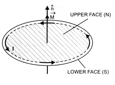
The magnetic dipole moment of the current loop (M) is directly proportional to (i) strength of current (I) through the loop and (ii) area (A) enclosed by the loop.
i.e., M I and M A
M = K I A _______ (1)
where K is a constant of proportionality.
If we define unit magnetic dipole moment as that of a small one turn loop of unit area carrying unit current, then from (1),
1 = K × 1 × 1 or K = 1
∴ from (1), M = IA
For N such turns, _______ (2)
The SI unit of M is ampere metre2.
One ampere metre2 is the magnetic moment of one turn loop of area one square metre carrying a current of one ampere.
In vector form, we can rewrite Eqn. (2) as
_______ (3)
where is unit vector perpendicular to the plane of the loop in a direction given by right handed screw rule.
The factor NI is called ampere turns of the circular current loop. Thus magnetic dipole moment of current loop = ampere turns x area of the loop.
Note that eqn. (2) is valid for planar current loop of any shape and size.
9. BAR MAGNET AS AN EQUIVALENT SOLENOID
We know that a current loop acts as a magnetic dipole. According to Ampere’s hypothesis, all magnetic phenomena can be explained in terms of circulating currents.
In given figure, magnetic field lines for a bar magnet and a current carrying solenoid resemble very closely. Therefore, a bar magnet can be thought of as a large number of circulating currents in analogy with a solenoid.
Cutting a bar magnet is like cutting a solenoid. We get two smaller solenoids with weaker magnetic properties. The magnetic field lines remain continuous, emerging from one face of one solenoid and entering into other face of other solenoid. If we were to move a small compass needle in the neighbourhood of a bar magnet and a current carrying solenoid, we would find that the deflections of the needle are similar in both cases.
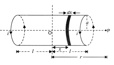
To demonstrate the similarity of a current carrying solenoid to a bar magnet, let us calculate axial field of a finite solenoid carrying current.
In the given figure, suppose
a = radius of solenoid,
2l = length of solenoid with centre O
n = number of turns per unit length of solenoid,
i = strength of current passed through the solenoid
We have to calculate magnetic field at any point P on the axis of solenoid, where OP = r. Consider a small element of thickness dx of the solenoid, at a distance x from O.
Number of turns in the element = n dx.
We know that magnitude of magnetic field at P due to this current element is
_______ (1)
If P lies at a very large distance from O, i.e., r > > a and r > > x, then [(r – x)2 + a2]3/2 = r3
_______ (2)
As range of variation of x is from x = -l to x = +l, therefore the magnitude of total magnetic field at P due to current carrying solenoid
_______ (2)
If M is magnetic moment of the solenoid, then
M = total no. of turns × current × area of cross section
M = n (2l) × i × ( a2)
_______ (4)
This is the expression for magnetic field on the axial line of a short bar magnet.
Thus, the axial field of a finite solenoid carrying current is same as that of a bar magnet. Hence, for all practical purposes, a finite solenoid carrying current is equivalent to a bar magnet.
3. MAGNETIC FIELD STRENGTH DUE TO A BAR MAGNET
The strength of magnetic field at any point is defined as the force experienced by a hypothetical unit north pole placed at that point.
It is a vector quantity. The direction of magnetic field () is the direction along which hypothetical unit north pole would tend to move if free to do so.
1. MAGNETIC FIELD STRENGTH AT A POINT ON AXIAL LINE OF A BAR MAGNET.
Let 2l be the magnetic length of a bar magnet with centre O. M is the magnetic dipole moment of the magnet, where M = m × 2l; OP = d, is the distance of the point P on the axial line from the centre of the magnet, (Figure).
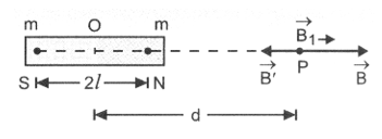
If m is the strength of each pole, then magnetic field strength at P due to N pole of magnet is
, along NP produced.
Magnetic field strength at P due to S pole of magnet,
, along PS
Magnetic field strength at P due to the bar magnet B1 = B – B’
_______ (1)
When the magnet is short, l2 << d2
_______ (2)
The direction of is along NP produced.
2. MAGNETIC FIELD STRENGTH AT A POINT ON EQUATORIAL LINE OF A BAR MAGNET.
In the given figure the point P is shown on equatorial line of the same bar magnet, where OP = d. Magnetic field strength at P due to N pole of magnet
, along NP produced.
Magnetic field strength at P does to S pole of magnet.
, along PS.
As B = B’ in magnitude, their components S sin along OP produced and B’ sin along PO cancel. However, components along PX parallel to NS add. Therefore,
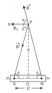
Magnetic field strength at P due to the bar magnet, B2 = B cos + B’ cos = 2 B’ cos , along PX
_______ (3)
If the magnet is short, l2 <<d2
_______ (4)
The direction of is along PX, a line parallel to NS, as shown in the above figure.
Dividing (2) by (4), we get
Hence, magnetic field due to a short bar magnet at any point on axial line of magnet is twice the magnetic field at a point at the same distance on the equatorial line of the magnet.
Note:
When point lies on axial line of magnetic dipole, it is known as end-on position or tangent A position. When point lies on equatorial line of magnetic dipole, it is known as broadside on position or tangent B position.
At any point on axial line of a dipole, magnetic field strength is along
At any point on equatorial line of a dipole, magnetic field strength is in a direction opposite to
4. TORQUE, POTENTIAL ENERGY & GAUSS LAW IN MAGNETISM
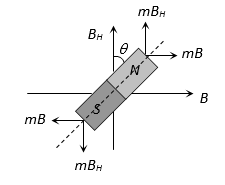
1. Torque on a bar magnet in a magnetic field
In Figure, a uniform magnetic field is represented by equidistant parallel lines. NS is a bar magnet of length 2l and strength of each pole = m.
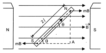
The magnet is held at with the direction of
Force on N-pole = m B, along
Force on S-pole = mB, opposite to
These forces being equal, unlike and parallel form a couple, which tends to rotate the magnet clockwise so as to align it along .
Draw NA perpendicular to and SA ||
∴ Torque acting on the bar magnet
= moment of the couple = force × perpendicular distance = mB × NA ______ (1)
In ΔNAS,
∴ NA = 2l sin
Put in (1), = mB × 2l sin. As M = m × 2l ______ (2)
In vector form, we can rewrite this equation as
The direction of is perpendicular to the plane containing , and is given by right handed screw rule.
When, B = 1 and = 90°, the from (2)
= M × 1 sin 90° = M or M =
Hence we may define
Magnetic dipole moment is the torque acting on a dipole held perpendicular to a uniform magnetic field of unit strength.
Unit of m is unit of x divided by unit of b. Therefore, the SI unit of is joule per tesla (JT-1).
2. Potential energy of a magnetic dipole in a magnetic field
Potential energy of a magnetic dipole in a magnetic field is the energy possessed by the dipole due to its particular position in the field.
When a magnetic dipole of moment is held at an angle 9 with the direction of a uniform magnetic field , the magnitude of the torque acting on the dipole is
= MB sin ______ (1)
This torque tends to align the dipole in the direction of the field. Work has to be done in rotating the dipole against the action of the torque. This work done is stored in the magnetic dipole as potential energy of the dipole.
Now, small amount of work done in rotating the dipole through a small angle dQ against the restoring
torque is dW = d = MB sin d
Total work done in rotating the dipole from = 1 to = 2 is
Potential energy of the dipole is ______ (2)
When 1 = 90°, and 2 = , then U = W = – MB (cos – cos 90°)
W =-MB cos ______ (3)
In vector notation, we may rewrite (3) as
______ (4)
Special Cases
1. When = 90°
U = – MB cos = – MB cos 90° = 0
i.e, when the dipole is perpendicular to magnetic field its potential energy is zero.
Hence to calculate potential energy of dipole at any position making angle with B, we use
U = -MB (cos 2 – cos 1) and take 1 = 90° and 2 = . Therefore,
U = -MB (cos – cos 90°) = – MB cos
2. When = 0°
U = – MB cos 0° = – MB,
which is minimum. This is the position of stable equilibrium, i.e., when the magnetic dipole is aligned along the magnetic field, it is in stable equilibrium having minimum P.E.
3. When = 180°
U = – MB cos 180° = MB, which is maximum. This is the position of unstable equilibrium.
3. MAGNETISM AND GAUSS’S LAW
According to Gauss’s law for magnetism, the net magnetic flux (B) through any closed surface is always zero.
The law implies that the number of magnetic field lines leaving any closed surface is always equal to the number of magnetic field lines entering it.
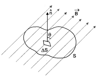
Suppose a closed surface S is held in a uniform magnetic field . Consider a small vector area element of this surface, In the given figure Magnetic flux through this area element is defined as . Summing over all small area elements of the surface, we obtain according to Gauss’s law for magnetism.
______ (1)
If the area elements are really small, we can rewrite this equation as
______ (2)
Compare this equation with Gauss’s law in electrostatics, i.e., electric flux through a closed surface S is given by
______ (3)
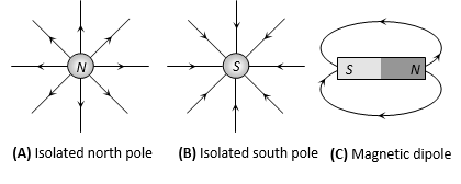
where q is electric charge enclosed by the closed surface. If an electric dipole were enclosed by the surface equal and opposite charges in the dipole add upto zero. Therefore, E would be zero. The fact that B = 0 indicates that the simplest magnetic element is a dipole or current loop. The isolated magnetic poles, called magnetic monopoles are not known to exist. All magnetic phenomena can be explained in terms of an arrangement of magnetic dipoles and/or current loops.
Gauss’s theorem in magnetism establishes that:
(i) isolated magnetic poles called monopoles do not exist, or
(ii) in magnetism, there is no counterpart of isolated free charge in electricity, or
(iii) magnetic poles always exist in unlike pairs of equal strength. Thus corresponding to eqn. (3) of Gauss’s theorem in electrostatics, we can visualize eqn. (2) as
where m is strength of N-pole and – m is strength of S-pole of same magnet. 0 is absolute magnetic permeability of free space.
DO YOU KNOW
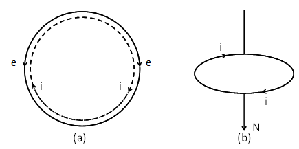
There can be magnets with no poles. For example, a magnetised ring (called toroid) or a solenoid of infinite length has properties of a magnet, but no poles, Figure.(a)

Figure(b) represents a magnet with two similar poles or with three poles. This may be due to faulty magnetisation of a bar. We find identical poles at the two ends with an opposite pole of double strength at the centre of the bar.
4. THE ELECTROSTATIC ANALOGUE OF MAGNETISM
We have studied that two unlike magnetic poles of equal strength (m) separated by a distance (2) form a magnetic dipole. It has a magnetic moment = m (2), which is directed’ from south to north through the magnet.
The magnetic dipole is analogous to an electric dipole, which consists of two equal charges of opposite sign (± q) separated by a certain distance (2 ). It has an electric dipole moment , which is directed from – q to + q.
The equations for magnetic field due to a magnetic dipole (or bar magnet) can be obtained from the equations of electric field due to an electric dipole by making the following changes:
Therefore, for any point on axial line of bar magnet at a distance (d) from the centre of magnet, we write
And for any point on equatorial line of bar magnet at a distance (d) from the centre of magnet, we write
In both the cases, we assume that length of magnet (2l) < < d i.e., the magnet is short.
Further, torque on magnetic dipole in an external magnetic field is
This corresponds to torque on electric dipole in an external electric field as
Similarly, the potential energy of magnetic dipole in an external magnetic field is
This corresponds to potential energy of an electric dipole in an external electric field as
Note:
There is one fundamental difference between electricity and magnetism. Whereas in electricity, an isolated charge can exist; in magnetism, an isolated magnetic pole does not exist. The simplest magnetic structure that can exist is only a magnetic dipole or current loop characterized by magnetic dipole moment . This is unlike a scalar charge q which characterizes electricity.
In an external magnetic field, the magnetic dipole experiences a torque (unlike the force experienced by a charge q in an external electric field). The effect of torque is to align the dipole along the external magnetic field. The directive property of a magnet is attributed to the torque acting on the magnetic dipole in the magnetic field of earth.
| The dipole analogy | ||
| Electrostatics | Magnetism | |
| 1/0 | μ0 | |
| Dipole moment | p | m |
| Equatorial field for a short dipole | –p/4πε0r3 | – μ0 m / 4π r3 |
| Axial Field for a short dipole | 2p/4πε0r3 | μ0 2m / 4π r3 |
| External Field: torque | p × E | m × B |
| External Field: Energy | -p.E | -m.B |
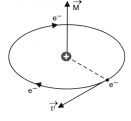
5. MAGNETIC DIPOLE MOMENT OF AN ATOM DUE TO REVOLVING
In every atom, electrons revolve around the nucleus. A revolving electron is like a loop of current, which has a definite magnetic dipole moment. When electron revolves in anticlockwise direction, the equivalent current is clockwise Figure.(a). Therefore, upper face of the electron loop acts as south pole and lower face acts as north pole Figure.(b). Hence an atom behaves as a magnetic dipole.
If e is the charge on an electron revolving in an orbit of radius r with a uniform angular velocity , then equivalent current
where T = the period of revolution of electron = 2/
___________ (1)
Area of the orbit A = r2
Magnetic moment of the atom is given by
___________ (2)
According to Bohr’s theory, an electron in an atom can revolve only in certain stationary orbits – in which angular momentum of electron (m v r) is an integral multiple of h/2, where h is Planck’s constant.
Thus, , where n = 1, 2, 3 …… denotes the number of the orbit. Using v = r, we get
___________ (3)
Put in (2), ___________ (4)
where ___________ (5)
From (3), it is clear that the magnetic moment of an atom is quantized having values 1 μB, 2μB, 3μB and so on, where μB is the least value of atomic dipole moment, . This is called Bohr Magneton. It serves as the unit of atomic magnetic dipole moment. We can calculate its value.
___________ (6).
. We may define
Bohr magneton as the minimum magnetic dipole moment associated with an atom due to orbital motion of an electron in the first stationary orbit of the atom.
Again, we define, Gyromagnetic ratio of electron =
5. EARTH’S OR TERRESTRIAL MAGNETISM
1. EARTH’S MAGNETIC FIELD (TERRESTRIAL MAGNETISM)
As per the most established theory it is due to the rotation of the earth where by the various charged ions present in the molten state in the core of the earth rotate and constitute a current.
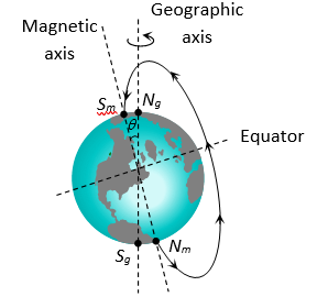
(1) The magnetic field of earth is similar to one which would be obtained if a huge magnet is assumed to be buried deep inside the earth at it’s centre.
(2) The axis of rotation of earth is called geographic axis and the points where it cuts the surface of earth are called geographical poles (Ng, Sg). The circle on the earth’s surface perpendicular to the geographical axis is called equator.
(3) A vertical plane passing through the geographical axis is called geographical meridian.
(4) The axis of the huge magnet assumed to be lying inside the earth is called magnetic axis of the earth. The points where the magnetic axis cuts the surface of earth are called magnetic poles. The circle on the earth’s surface perpendicular to the magnetic axis is called magnetic equator.
(5) Magnetic axis and Geographical axis don’t coincide but they make an angle of 17.5° with each other.
(6) Magnetic equator divides the earth into two hemispheres. The hemisphere containing south polarity of earth’s magnetism is called northern hemisphere while the other, the southern hemisphere.
(7) The magnetic field of earth is not constant but changes irregularly from place to place on the surface of the earth and even at a given place it varies with time too.
(8) Direction of earth’s magnetic field is from S (geographical south) to N (geographical north).
2. ELEMENTS OF EARTH’S MAGNETIC FIELD
The magnitude and direction of the magnetic field of the earth at a place are completely given by certain. quantities known as magnetic elements.
1. MAGNETIC DECLINATION ()
It is the angle between geographic and the magnetic meridian planes.
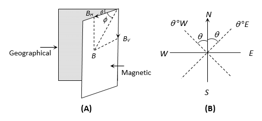
Declination at a place is expressed at or depending upon whether the north pole of the compass needle lies to the east or to the west of the geographical axis.
2. ANGLE OF INCLINATION OR DIP ()
It is the angle between the direction of intensity of total magnetic field of earth and a horizontal line in the magnetic meridian.
3. HORIZONTAL COMPONENT OF EARTH’S MAGNETIC FIELD (BH)
Earth’s magnetic field is horizontal only at the magnetic equator. At any other place, the total intensity can be resolved into horizontal component (BH) and vertical component (BV).
Also BH = …… (i) and
…… (ii)
By squaring and adding equation (i) and (ii)
Dividing equation (ii) by equation (i)
3. MAGNETIC MAPS AND NEUTRAL POINTS
MAGNETIC MAPS
Magnetic maps (i.e. Declination, dip and horizontal component) over the earth vary in magnitude from place to place. It is found that many places have the same value of magnetic elements. The lines are drawn joining all place on the earth having same value of a magnetic element. These lines form magnetic map.
(i) Isogonic lines: These are the lines on the magnetic map joining the places of equal declination.
(ii) Agonic line: The line which passes through places having zero declination is called agonic line.
(iii) Isoclinic lines: These are the lines joining the points of equal dip or inclination.
(iv) Aclinic line: The line joining places of zero dip is called aclinic line (or magnetic equator)
(v) Isodynamic lines : The lines joining the points or places having the same value of horizontal component of earth’s magnetic field are called isodynamic lines.
NEUTRAL POINTS
A neutral point is a point at which the resultant magnetic field is zero. In general the neutral point is obtained when horizontal component of earth’s field is balanced by the field produced by the magnet.
6. MAGNETIC MATERIALS AND RELATED LAWS
1. DIAMAGNETIC MATERIALS (DIAMAGNETISM)
The diamagnetic substances are those in which the individual atoms/molecules/ions do not possess any net magnetic moment on their own. When such substances are placed in an external magnetising field, they get feebly magnetised in a direction opposite to the magnetising field.
Examples: Antimony, Bismuth, Copper, Lead, Gold, Silver, Diamond, Zinc, Quartz; Water, Alcohol, Mercury; Air, Hydrogen, Nitrogen and all inert gases like Helium, Neon, Argon etc.
IMPORTANT PROPERTIES OF DIAMAGNETIC SUBSTANCES
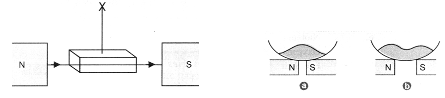
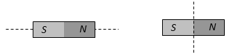
(i) When suspended in a uniform magnetic field, they set their longest axis at right angles to the direction of the field, i.e., the shortest axis is along the direction of the field. This is shown in Figure.

(ii) When placed in a non-uniform magnetic field, these substances have a tendency to move from stronger parts of the field to the weaker parts. For example, consider a diamagnetic liquid put in a watch glass placed on two pole pieces of an electromagnet held close to each other ( 2 mm or so). When the current is switched on, the liquid level acquires the shape shown in Figure(a). The liquid accumulates on the sides where field is weaker. The depression in the middle is due to stronger field at the centre. If the distance between the poles is increased, the effect is reversed, as in this case, the field is weaker at the centre. This is shown in Figure (b).
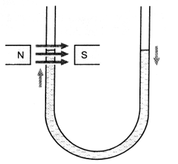
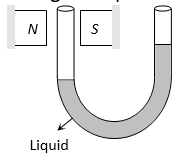
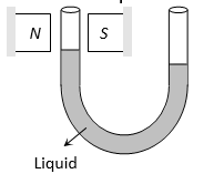
(iii) The level of a diamagnetic liquid in U tube is depressed, in the limb which is between the poles of a strong magnet as shown in figure. It confirms movement of diamagnetics from stronger parts of the field to weaker parts. This property implies that whereas a magnet attracts metals like iron, it would repel a diamagnetic substance like copper.

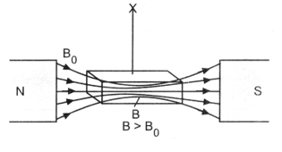
(iv) When a specimen of a diamagnetic material is placed in a magnetising field, the magnetic field lines prefer not to pass through the specimen, (figure). It implies that the magnetic field lines are repelled or expelled and the field inside the material is reduced. This reduction is slight, being one part in 105.
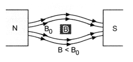
(v) Relative magnetic permeability of diamagnetic substances is always less than unity.
and B < B0
∴ μr < 1
(vi) From the relation μr = (1 + m), as μr < 1, m is negative. Hence susceptibility of diamagnetic substances has a small negative value.
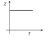
(vii) Susceptibility of diamagnetics does not change with temperature. Bismuth at low temperature is an exception to this general property.
Values of Magnetic susceptibility of some diamagnetic substances at room temperature (300 K) are given in table.
|
Magnetic susceptibility of some diamagnetic substances at 300 K |
||
|
S.No |
Diamagnetic substance |
m |
|
1. |
Copper |
– 9.6 × 10⁻⁶ |
|
2. |
Lead |
-1.6 × 10⁻⁵ |
|
3. |
Diamond |
– 2.2 × 10⁻⁵ |
|
4. |
Gold |
– 3.6 × 10⁻⁵ |
|
5. |
Water |
-9.1 × 10⁻⁶ |
|
6. |
Mercury |
– 3.2 × 10⁻⁵ |
|
7. |
Hydrogen |
-2.1 x 10⁻⁹ |
|
8. |
Nitrogen |
– 5.0 × 10⁻⁹ |
|
9. |
Bismuth |
– 1.6 × 10⁻⁶ |
|
10. |
Silver |
– 2.6 × 10⁻⁵ |
|
11. |
Silicon |
– 4.2 × 10⁻⁵ |
UNDERSTANDING DIAMAGNETISM
We know that each electron in an atom is revolving in an orbit around the nucleus. The revolving electron is equivalent to a tiny loop of current. Therefore, it possesses some orbital magnetic dipole moment
= current × area of the loop.
In addition to the orbital motion, every electron is assumed to have a spin motion around its axis.
Therefore, another dipole magnetic moment called spin magnetic moment is also associated with electron.
The vector sum of and provides the net magnetic dipole moment to the atom.
In a diamagnetic substance, and cancel each other for every atom so that the atom has no net magnetic dipole moment.
Therefore, motion of all the electrons in an atom of a diamagnetic material is assumed to be reduced to motion of two electrons revolving with same angular velocity in a circular orbit of same radius, but in opposite sense.
The magnetic moment of the two being equal and opposite, cancel each other (in the absence of any external magnetic field) so that net magnetic moment of each atom is zero.
Let a uniform external magnetic field of induction be applied perpendicular to the plane of rotation of electron and directed away from the reader. Each electron experiences a magnetic Lorentz force F = Bev. According to Fleming’s left hand rule, the Lorentz force F acts radially outwards on the electron revolving anti-clockwise. It tends to decrease the centripetal force and hence decrease the velocity of electron to (). As a result, the magnetic moment of electron decreases to (),(Figure). On the electron revolving clockwise, the Lorentz force acts radially inwards, tending to increase the centripetal force and hence the velocity of electron to (). Therefore, the magnetic moment of electron increases to (),(Figure). The vector addition of these two magnetic moments gives rise to a net dipole magnetic moment 2 , directed towards the reader i.e. opposite to external field .
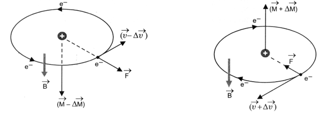
The net magnetic moment 2 so developed is called induced magnetic moment. The magnetic moments induced in different atoms add vectorially to give a net magnetisation of the material in a direction opposite to . This accounts for the diamagnetic behaviour of materials. Further, as the appearance of induced magnetic moment in atoms is not affected by the thermal motion of the atoms, therefore, magnetic susceptibility of such materials does not depend on temperature of the materials.
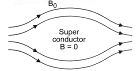
SUPER CONDUCTORS
Superconductors are the most exotic diamagnetic materials. These are metals cooled to very low temperatures, which have zero resistance, i.e., perfect conductivity is associated with perfect diamagnetism. The magnetic field lines are completely expelled from superconductors, as shown in figure.
i.e., relative magnetic permeability of superconductors is zero
As
∴ i.e., magnetic susceptibility of superconductors is minus one. A superconductor repels a magnet and in turn, is repelled by the magnet. The phenomenon of perfect diamagnetism in superconductors is called Meissner effect. Superconducting magnets have been used for running magnetically leviated superfast trains.
2. PARAMAGNETIC MATERIALS (PARAMAGNETISM)
Paramagnetic substances are those in which each individual atom/molecule/ion has a net non zero magnetic moment of its own. When such substances are placed in an external magnetic field, they get feebly magnetised in the direction of the magnetising field.
Examples: Aluminium, Chromium, Manganese, Lithium, Magnesium, Platinum, Tungsten, Sodium, Potassium, Copper chloride, Oxygen, etc.
IMPORTANT PROPERTIES OF PARAMAGNETIC SUBSTANCES
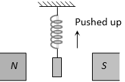
(i) When suspended in a uniform magnetic field, they rotate so as to bring their longest axis along the direction of the field. This is shown in figure.
(ii) When placed in a non-uniform magnetic field, they tend to move from weaker parts of the field to the stronger parts. It implies that paramagnetic substances get weakly attracted to a magnet. For example, consider a paramagnetic powder or liquid put in a watch glass placed on two pole pieces of an electromagnet held close to each other (2 mm or so). As the current is switched on, the liquid level acquires a shape shown in Figure.(a), accumulating at the centre, where the field is the strongest. If the distance between the poles is increased, the effect is reversed, as in that case, the field is weaker at the centre. This is shown in Figure. (b).
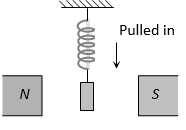
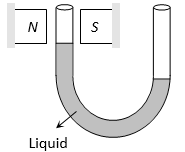
(iii) When a magnetic field is applied to the level of a paramagnetic liquid in one limb of a U-tube, the liquid level rises as shown in figure. It confirms that paramagnetic substances move from weaker to stronger parts of the magnetic field.
(iv) When a specimen of a paramagnetic substance is placed in a magnetising field, the magnetic field lines prefer to pass through the specimen rather than through air, as shown in figure. Thus magnetic induction B inside the sample is more than the magnetic induction Bo outside the sample, i.e., B > B0. This enhancement is slight, being one part in 105.
(v) Relative magnetic permeability of paramagnetic substances is always more than unity.
As and B > B0
∴ μr > 1
It means paramagnetic substances have a tendency to pull in magnetic field lines when placed in a magnetising field.
(vi) From the SI relation, μr = 1 + m, as μr > 1, therefore, m must be positive. Hence, susceptibility of paramagnetic substances is positive, though small.
Values of magnetic susceptibility of some paramagnetic substances at room temperature ( 300 K) are given in table
|
Magnetic susceptibility of some diamagnetic substances at 300 K |
||
|
S.No |
Diamagnetic substance |
cm |
|
1. |
Aluminium |
2.3 × 10⁻⁵ |
|
2. |
Calcium |
1.9 ×10⁻⁵ |
|
3. |
Chromium |
2.7 × 10⁻⁴ |
|
4. |
Lithium |
2.1 × 10⁻⁵ |
|
5. |
Magnesium |
1.2 × 10⁻⁵ |
|
6. |
Niobium |
2.6 × 10⁻⁵ |
|
7. |
Oxygen (STP) |
2.1 × 10⁻⁶ |
|
8. |
Platinum |
2.9 × 10⁻⁴ |
|
9. |
Tungsten |
6.8 × 10⁻⁵ |
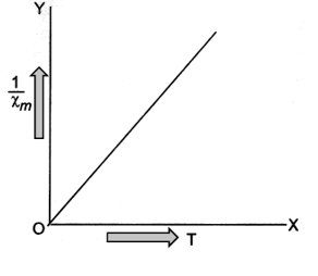
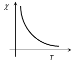
(viii) Susceptibility of paramagnetic substances varies inversely as the temperature of the substance i.e. they lose their magnetic character with rise in temperature. The graph between temperature T and (1/) is a straight line as shown in figure.
UNDERSTANDING OF PARAMAGNETISM
In paramagnetic materials, every atom has some permanent magnetic dipole moment. In the absence of an external magnetic field, the atomic dipoles are randomly oriented so that average magnetic moment per unit volume of the material is zero. Therefore, a paramagnetic material does not behave as a magnet in the absence of an external magnetic field,(Figure)
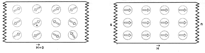
When an external magnetic field is applied, it tries to align the atomic magnetic dipoles in the direction of the field, (Figure). That is why the specimen gets magnetised weakly in the direction of the field. This is paramagnetism.
When we raise the temperature of the material, the atomic magnetic dipoles acquire some kinetic energy. This tends to disorient the dipoles. That is why magnetic susceptibility of the paramagnetic materials decreases with rise in temperature.
3. FERROMAGNETIC MATERIALS (FERROMAGNETISM)
Ferromagnetic substances are those in which each individual atom/molecule/ion has a non zero magnetic moment, as in a paramagnetic substance.
When such substances are placed in an external magnetising field, they get strongly magnetised in the direction of the field.
Examples: Iron, Cobalt, Nickel, Gadolinium and a number of their alloys.
The ferromagnetic materials show all the properties of paramagnetic substances, but to a much greater degree. For example,
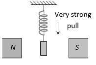
(i) They are strongly magnetised in the direction of external field in which they are placed.
(ii) They have a strong tendency to move from a region of weak magnetic field to the region of strong magnetic field, i.e. they get strongly attracted to a magnet.
(iii) Relative magnetic permeability of ferromagnetic materials is very large (103 to 105)
(iv) The susceptibility of ferromagnetic materials is also very large. That is why they can be magnetised easily and strongly. ( m = r – 1)
(v) With rise in temperature, susceptibility of ferromagnetics decreases. At a certain temperature, ferromagnetics change over to paramagnetics. This transition temperature is called curie temperature. For example, curie temperature of iron is about 1000 K.
EXPLANATION OF FERROMAGNETISM
Ferromagnetism has been explained by Weiss on the basis of domain theory in addition to the usual electron theory.
Like paramagnetic substances, each atom of a ferromagnetic substance is a tiny magnetic dipole having permanent dipole moment. However, in ferromagnetic materials, atoms form a very large number of small effective regions called domains. Each domain has a linear dimension 1000 A° and contains about 1010 atoms. Within each domain, a special interaction called exchange coupling renders dipole moments of all the atoms in a particular direction. Thus each domain is a strong magnet without any external magnetic field. Inspite of this, a ferromagnetic substance does not behave as a magnet, because in the absence of external magnetic field, the magnetic moments of different domains are randomly oriented so that their resultant magnetic moment in any direction is zero, (Figure a).
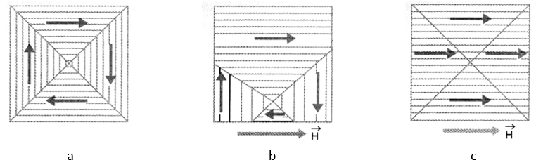
When an external magnetic field is applied on the ferromagnetic substance, it gets strongly magnetised. This can be understood in terms of
(i) displacement of boundaries of the domains i.e. domains which are oriented in the direction of applied field increase in size and the domains which are oriented opposite to the field decrease in size, figure.b.
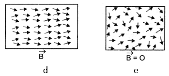
(ii) rotation of the domains i.e. the domains rotate till their magnetic moments are aligned in the direction of the applied magnetic field, figure.c. This would happen only when the magnetic field applied is very strong. Figure.45 shows the state when the domains have partially aligned along and amalgamated to form a single giant domain. This is how ferromagnetic material gets strongly magnetised in the direction of the applied field. In contrast, Figure (e) shows the state when .
When external magnetic field is removed, magnetization disappears in some of the materials like soft iron. These materials are called soft ferromagnets. However, in materials like Alnico (an alloy of iron, aluminium, nickel, cobalt and copper), the magnetization persists even after removal of external magnetic field. Such materials are called hard ferromagnets.
Further, when a ferromagnetic material is heated, its magnetization decreases gradually with rise in temperature. At a particular temperature, ferromagnetic material changes over to paramagnetic material. This is because the domain structure disintegrates with rise in temperature. The temperature of transition from ferromagnetism to paramagnetism is called the Curie temperature. It is different for different ferromagnetic materials as shown in table
|
Curie temperature of some ferromagnetic materials |
|
|
Material |
Curie Temperature |
|
Cobalt Iron Fe2O3 Nickel Gadolinium |
1394 K 1043 K 893 K 631 K 317 K |
Table displays the values of susceptibility (m), relative magnetic permeability (μr) and absolute magnetic permeability (μ) of the three types of magnetic substances.
| m, r and μ of magnetic substances | |||
| Substance | m | μr | μ |
| Diamagnetic | -1 m < 0 | 0 μr < 1 | μ < μ0 |
| Paramagnetic | 0 < m < | 1 < μr < (1 + ) | μ > μ0 |
| Ferromagnetic | m > > 1 | μr > > 1 | μ > > μ0 |
| Note: is a positive number | |||
DO YOU KNOW
Apart from dia, para and ferro magnetism, recently some new kinds of magnetism have also been discovered, e.g. ferrimagnetism; antiferromagnetism; Meta and parasitic ferromagnetism. The existence of domains and their motion in applied magnetic field can be observed under a microscope, after sprinkling a liquid suspension of powdered ferromagnetic substance.
COMPARATIVE STUDY OF MAGNETIC MATERIALS
COMPARATIVE STUDY OF MAGNETIC MATERIALS
|
Property |
Diamagnetic substances |
Paramagnetic substances |
Ferromagnetic substances |
|
Cause of magnetism |
Orbital motion of electrons |
Spin motion of electrons |
Formation of domains |
|
Explanation of magnetism |
On the basis of orbital motion of electrons |
On the basis of spin and orbital motion of electrons |
On the basis of domains formed |
|
Behaviour In a non-uniform magnetic field |
These are repelled in an external magnetic field i.e. have a tendency to move from high to low field region.
|
These are feebly attracted in an external magnetic field i.e., have a tendency to move from low to high field region
|
These are strongly attracted in an external magnetic field i.e. they easily move from low to high field region
|
|
State of magnetisation |
These are weekly magnetised in a direction opposite to that of applied magnetic field |
These get weekly magnetised in the direction of applied magnetic field |
These get strongly magnetised in the direction of applied magnetic field |
|
When the material in the form of liquid is filled in the U-tube and placed between pole pieces.
|
Liquid level in that limb gets depressed
|
Liquid level in that limb rises up
|
Liquid level in that limb rises up very much
|
|
On placing the gaseous materials between pole pieces |
The gas expands at right angles to the magnetic field. |
The gas expands in the direction of magnetic field. |
The gas rapidly expands in the direction of magnetic field |
|
The value of magnetic induction B |
B < B0 (where B0 is the magnetic induction in vacuum) |
B > B0 |
B >> B0 |
|
Magnetic susceptibility |
Low and negative || 1 |
Low but positive 1 |
Positive and high 102 |
|
Dependence of on temperature |
Does not depend on temperature (except Bi at low temperature)
|
On cooling, these get converted to ferromagnetic materials at Curie temperature
|
These get converted into paramagnetic materials at Curie temperature
|
|
Relative permeability (μr) |
μr < 1 |
μr > 1 |
μr >> 1 μr = 102 |
|
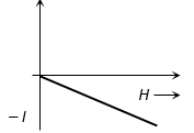
Intensity of magnetisation (I) |
I is in a direction opposite to that of H and its value is very low |
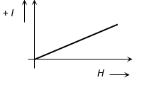
I is in the direction of H but value is low |
I is in the direction of H and value is very high. |
|
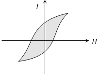
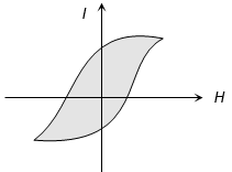
I-H curves |
|
|
|
|
Magnetic moment (M) |
Very low ( 0) |
Very low |
Very high |
|
Examples |
Cu, Ag, Au, Zn, Bi, Sb, NaCl, H2O air and diamond etc. |
Al, Mn, Pt, Na, CuCl2, O2 and crown glass |
Fe, Co, Ni, Cd, Fe3O4 etc. |
4. CURIE LAW
According to Curie law,
Intensity of magnetisation (I) of a magnetic material is (i) directly proportional to magnetic induction (B), and (ii) inversely proportional to the temperature (T) of the material.
i.e., I B, and
Combining these factors, we get
As B H, magnetizing intensity
But
where C is a constant of proportionality and is called Curie constant.
Thus for a paramagnetic material, both m and r depend not only on the material, but also on the sample temperature.
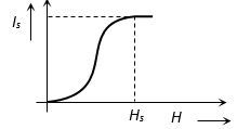
The law is physically reasonable as increasing H tends to align the elementary dipoles in the specimen increasing I, whereas increasing T, tends to interfere with this alignment, decreasing I. The variation of I with H/T is shown in figure.
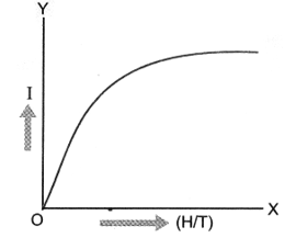
At very high fields or at very low temperatures, the magnetisation approaches its maximum value, when all atomic dipole moments are aligned. This is called the saturation magnetisation value, as is indicated by the portion of graph parallel to X-axis.
Note that magnetic thermometers are based on Curie law. These thermometers are used to measure very low temperatures (< 1 K) by measuring the susceptibility of a paramagnetic substance. Curie’s law is well verified experimentally provided the ratio H/T is not too large.
Note:
The susceptibility of ferromagnetics, above the Curie temperature i.e. in the paramagnetic phase is given by
where Tc is Curie temperature and sample temperature T > TC. This is the form Curie law assumes for ferromagnetic materials above the Curie temperature.
5. CURIE TEMPERATURE
The temperature above which a ferromagnetic material behaves like a paramagnetic material is defined as Curie temperature (Tc).
or
The minimum temperature at which a ferromagnetic substance is converted into paramagnetic substance is defined as Curie temperature. For various ferromagnetic materials its values are different, e.g. for Ni, for Fe, for CO,
At this temperature the ferromagnetism of the substances suddenly vanishes
6. CURIE-WEISS LAW
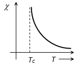
At temperatures above Curie temperature the magnetic susceptibility of ferromagnetic materials is inversely proportional to (T – Tc)
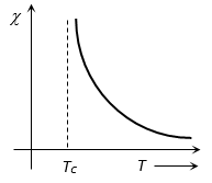
i.e.
Here Tc = Curie temperature
-T curve is shown (for Curie-Weiss Law)
7. HYSTERESIS CURVE
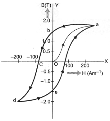
The hysteresis curve represents the relation between magnetic induction (or intensity of magnetization ) of a ferromagnetic material with magnetizing force or magnetic intensity . The shape of the hysteresis curve is shown in figure.. It represents the behaviour of the material as it is taken through a cycle of magnetization.
Suppose the material is unmagnetised initially, i.e., = 0 and . This state is represented by the origin O. We place the material in a solenoid and increase the current through the solenoid gradually. The magnetising force increases. The magnetic induction in the material increases and saturates as depicted in the curve oa.
This behaviour represents alignment and merger of the domains of ferromagnetic material until no further enhancement in is possible. Therefore, there is no use of increasing solenoid current and hence magnetic intensity beyond this.
Next, we decrease the solenoid current and hence magnetic intensity till it reduces to zero. The curve follows the path ab showing that when . Thus, some magnetism is left in the specimen.
The value of magnetic induction left in the specimen when the magnetising force is reduced to zero is called Retentity or Remanence or Residual magnetism of the material.
It shows that the domains are not completely randomised even when the magnetising force is removed.
Next, the current in the solenoid is reversed and increased slowly. Certain domains are flipped until the net magnetic induction inside is reduced to zero. This is represented by the curve be. It means to reduce the residual magnetism or retentivity to zero, we have to apply a magnetising force = OC in opposite direction. This value of magnetising force is called coercivity of the material.
As the reverse current in solenoid is increased in magnitude, we once again obtain saturation in the reverse direction at d. The variation is represented by the curve cd. Next, the solenoid current is reduced (curve de), reversed and increased (curve ea). The cycle repeats itself. From the above figure, we find that saturated magnetic induction Bs is of the order of 1.5 T and coercivity is of the order of -90 Am–1.
From the above discussion, it is clear that when a specimen of a magnetic material is taken through a cycle of magnetisation, the intensity of magnetisation (I) and magnetic induction (B) lag behind the magnetising force (H). Thus, even if the magnetising force H is made zero, the values of I and B do not reduce to zero i.e., the specimen tends to retain the magnetic properties.
This phenomenon of lagging of I or B behind H when a specimen of a magnetic material is subjected to a cycle of magnetisation is called hysteresis.
From the above figure, we make the following observations:
(i) For a given value of H; value of B or I is not unique, but depends on previous history of the sample.
(ii) No segment O a, ab etc. of the hysteresis curve is linear. Therefore, B or I is not proportional to H over any appreciable range.
Note:
1. We can plot I-H loop in the same way as we have plotted B-H loop of the ferromagnetic material. The shapes of I-H loop and B-H loop for a given material are identical.
2. that has the dimensions of energy per unit volume. That is why area within the BH loop represents energy dissipated per unit volume in the material.
8. ENERGY DISSIPATION DUE TO HYSTERESIS
When a magnetic material is taken through a cycle of magnetisation, some energy is spent in the process. The energy cannot be recovered and is dissipated in the form of heat in the specimen. Infact, when a specimen is taken through a cycle of magnetisation, the molecular magnets (magnetic dipoles) in the specimen are oriented and reoriented time and again. This molecular motion within the specimen results in the production of heat. It can be shown that the loss of energy per unit volume of specimen per cycle of magnetisation in cgs system is equal to the area of the I-H loop of the specimen and in SI, it is equal to the area of the B-H loop. The exact shape and size of the I-H and B-H loops depend upon the nature of the material and history of the specimen. By studying the hysteresis loops of various magnetic materials, we can study the difference in their properties e.g., retentivity, coercivity, permeability, susceptibility and energy loss etc. Such studies enable us to select suitable materials for different purposes e.g. for electromagnets, for transformer cores, for permanent magnets etc.
For example, hysteresis loop for soft iron is narrow and large, whereas the hysteresis loop for steel is wide and short,(Figure)
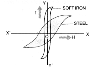
The hysteresis loops of soft iron and steel reveal that
(i) The retentivity of soft iron is greater than the retentivity of steel,
(ii) Soft iron is more strongly magnetised than steel,
(iii) Coercivity of soft iron is less than coercivity of steel. It means soft iron loses its magnetism more rapidly than steel does.
(iv) As area of I-H loop for soft iron is smaller than the area of I-H loop for steel, therefore, hysteresis loss in case of soft iron is smaller than the hysteresis loss in case of steel.
COMPARISON BETWEEN SOFT IRON AND STEEL
|
Soft iron |
Steel |
 |
 |
|
The area of hysteresis loop is less (low energy loss) |
The area of hysteresis loop is large (high energy loss) |
|
Less relativity and corecive force |
More retentivity and corecive force |
|
Magnetic permeability is high |
Magnetic permeability is less |
|
I and c both are high |
I and c both are low |
|
It magnetised and demagnetised easily |
Magnetisation and demagnetisation is not easy |
|
Used in dynamo, transformer, electromagnet tape recorder and tapes etc. |
Used for making permanent magnet. |
9. USES OF FERRO MAGNETIC MATERIALS
Important properties of ferromagnetic materials are studied from their hysteresis curves. These properties help us in the proper selection of materials for various practical applications as detailed below:
(A) PERMANENT MAGNETS
Permanent magnets are the materials which retain at room temperature, their ferromagnetic properties for a long time. The material chosen should have
(i) high retentivity so that the magnet is strong,
(ii) high coercivity so that the magnetisation is not erased by stray magnetic fields, temperature changes or mechanical damage due to rough handling etc.
(iii) high permeability so that it can be magnetised easily.
Steel is preferred for making permanent magnets. Though retentivity of steel is slightly smaller than that of soft iron, yet its coercivity is much larger than that of soft iron. Other suitable materials for permanent magnets are cobalt steel, (52% iron, 36% cobalt, 7% tungsten, 4.0% chromium, 0.5% manganese and 0.5% carbon) and carbon steel (98% iron; 0.86% carbon and 0.9% manganese), the alloy alnico (55% iron, 10% aluminium, 17% nickel, 12% cobalt and 6% copper).
An efficient way to make a permanent magnet is to place a ferromagnetic rod in a solenoid and pass current through the solenoid. The magnetic field of the solenoid magnetises the rod.
(B) ELECTROMAGNETS
The core of electromagnets are made of ferromagnetic materials, which have high permeability and low retentivity. Soft iron is a suitable material for this purpose. When a soft iron rod is placed in a solenoid and current is passed through the solenoid, magnetism of the solenoid is increased by a thousand fold. When the solenoid current is switched off, the magnetism is removed instantly as retentivity of soft iron is very low. Electromagnets are used in electric bells, loudspeakers and telephone diaphragms. Giant electromagnets are used in cranes to lift machinery etc.
(C) TRANSFORMER CORES
The materials used for making transformer cores, chokes, diaphragms of telephones etc. are subjected to ac cycle of magnetisation for a long period. Therefore, low hysteresis loss is the first essential condition for such materials. The hysteresis curve of such materials must be narrow. The energy dissipated and therefore, heating of the material will be small. The material chosen must also have high resistivity to decrease energy losses due to eddy currents. Soft iron is more suitable for transformer cores. More effective alloys have also been developed for the purpose. Some of them are perm alloys, mu metal (76% nickel, 17% iron, 5% copper and 2% chromium) and radio metal, etc.
DO YOU KNOW
That ferromagnetic materials have been divided into two types:
1. Soft magnetic materials, which have low retentivity, low coercivity and low hysteresis loss. Soft iron, mu metal and stalloy are some of the examples of these materials, used primarily for electromagnets, cores of transformers, motors and generators.
2. Hard magnetic materials, which have high retentivity, high coercivity and large hysteresis loss. Steel, alnico, alcomax and ticonal are some of the examples of these materials, which have been used for making permanent magnets of electric metres and loud speakers etc.
7. MAGNETISM MEASURING INSTRUMENTS
1. TANGENT LAW & TANGENT GALVANOMETER
TANGENT LAW
When a small magnet is suspended in two uniform magnetic fields and which are at right angles to each other, the magnet comes to rest at an angle with respect to .
In equilibrium
. This is called tangent law.
TANGENT GALVANOMETER
It consists of three circular coils of insulated copper wire wound on a vertical circular frame made of nonmagnetic material as ebonite or wood. A small magnetic compass needle is pivoted at the centre of the vertical circular frame. When the coil of the tangent galvanometer is kept in magnetic meridian and current passes through any of the coil then the needle at the centre gets deflected and comes to an equilibrium position under the action of two perpendicular field : one due to horizontal component of earth and the other due to field (B) set up by the coil due to current.
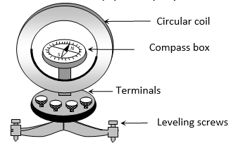
In equilibrium where ; n = number of turns, r = radius of coil, i = the current to be measured, = angle made by needle from the direction of BH in equilibrium.
Hence where is called reduction factor.
2. DEFLECTION MAGNETOMETER
It’s working is based on the principle of tangent law. It consists of a small compass needle, pivoted at the centre of a circular box. The box is kept in a wooden frame having two meter scale fitted on it’s two arms. Reading of a scale at any point directly gives the distance of that point from the centre of compass needle.
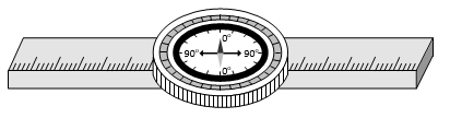
1. TAN A POSITION
In this position the magnetometer is set perpendicular to magnetic meridian. So that, magnetic field due to magnet, is in axial position and perpendicular to earth’s field. Hence or
2. TAN B POSITION
The arms of magnetometer are set in magnetic meridian, so that the magnetic field due to magnet is at it’s equatorial position. Hence or
3. COMPARISON OF MAGNETIC MOMENTS
According to deflection method
According to null deflection method
3. VIBRATION MAGNETOMETER
Vibration magnetometer is used for comparison of magnetic moments and magnetic fields. This device works on the principle, that whenever a freely suspended magnet in a uniform magnetic field, is disturbed from it’s equilibrium position, it starts vibrating about the mean position.

Time period of oscillation of experimental bar magnet (magnetic moment M) in earth’s magnetic field is given by the formula. ; where, I = moment of inertia of short bar magnet = (w = mass of bar magnet)
(1) Determination of magnetic moment of a magnet
The experimental (given) magnet is put into vibration magnetometer and it’s time period T is determined. Now
(2) Comparison of horizontal components of earth’s magnetic field at two places
; since I and M of the magnet are constant,
So
(3) Comparison of magnetic moment of two magnets of same size and mass
; Here I and BH are constants.
So
(4) Comparison of magnetic moments by sum and difference method
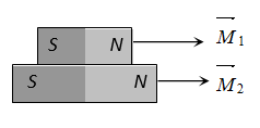
Sum position
Net magnetic moment Ms = M1 + M2
Net moment of inertia Is = I1 + I2
Time period of oscillation of this pair in earth’s magnetic field (BH)
….(i)
Frequency
Difference position
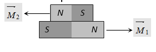
Net magnetic moment
Md = M1 + M2
Net moment of inertia Id = I1 + I2
and
….(ii)
and . From equation (i) and (ii) we get
(5) To find the ratio of magnetic field
Suppose it is required to find the ratio where B is the field created by magnet and BH is the horizontal component of earth’s magnetic field.
To determine a primary (main) magnet is made to first oscillate in earth’s magnetic field (BH) alone and it’s time period of oscillation (T) is noted.
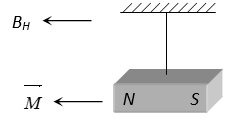
and frequency
Now a secondary magnet placed near the primary magnet so primary magnet oscillate in a new field with is the resultant of B and BH and now time period, is noted again.
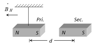
or
SOLVED EXAMPLES
1. A magnet of magnetic moment M and pole strength m is divided in two equal parts, then magnetic moment of each part will be
(A) M (B) M/2 (C) M/4 (D) 2M
Sol. B
If cut along the axis of magnet of length l, then new pole strength and new length l’ = l
∴ New magnetic moment
If cut perpendicular to the axis of magnet, then new pole strength m’ = m and new length, l’ = l/2
∴ New magnetic moment
2. An iron rod of volume and relative permeability 1000 is placed inside a long solenoid wound with 5 turns/cm. If a current of 0.5 A is passed through the solenoid, then the magnetic moment of the rod is
(A) 10 Am2 (B) 15 Am2 (C) 20 Am2 (D) 25 Am2
Sol. D
We have,
or
For a solenoid of n-turns per unit length and current i
H = ni
∴ Magnetic moment M=IV
= 25 Am2
3. A circular coil of 300 turns and diameter 14 cm carries a current of 15 A. What is the magnitude of the magnetic moment associated with the coil?
Sol. M = NIA = NI(r2)
= 69.3 J T–1
4. A straight solenoid of length 50 cm has 1000 turns per metre and a mean cross-sectional area of 2 × 10⁻⁴ m2. It is placed with its axis at 30°, with a uniform magnetic field of 0.32 T. Find the torque acting on the solenoid when a current of 2 ampere is passed through it.
Sol. Here, l = 50 cm.
Number of turns per metre = 1000
∴ Total no. of turns (N) = 1000 × = 500
A = 2 × 10⁻⁴ m2. I = 2 A
B = 0.32 T =?
= MB sin = (N I A) B sin
= 500 × 2 × (2 × 10–4) × 0.32 × = 0.032 Nm
5. A short bar magnet has a magnetic moment of 0.24 J T–1. Calculate the magnitude of the magnetic field produced by the magnet at a distance of 10 cm from the centre of the magnet, on the axis of the magnet.
Sol.
= 4.8 × 10⁻⁵ T
6. A magnet 2 cm long has a pole strength of 60 Am. Find the magnitude of magnetic field strength B at a point on its axis at a distance of 20 cm from it. What would be the value of B, if the point were to lie at the same distance on equatorial line of magnet?
Sol. Here, 2l = 2 cm = 0.02 m; m = 60 Am, B =?, d = 20 cm = 0.2 m
On axial line, as l < d,
At the same distance, on equatorial line,
7. Two identical magnetic dipoles of magnetic moments 1.0 A-m2 each, placed at a separation of 2m with their axis perpendicular to each other. The resultant magnetic field at a point midway between the dipoles is
(A) (B) (C) (D) None of these
Sol. B
With respect to 1st magnet, P lies in end side-on position
(RHS)
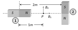
With respect to 2nd magnet. P lies in broad side on position.
(Upward)
As B1 and B2 are mutually perpendicular, hence the resultant magnetic field
8. A short bar magnet placed with its axis at 30° to a uniform magnetic field of 0.2 T experiences a torque of 0.06N m. (a) Calculate the magnetic moment of the magnet and (b) find out what orientation of the magnet corresponds to stable equilibrium in the magnetic field.
Sol. (a) = MB sin
or
(b) The magnet will be in stable equilibrium if it experiences not torque due to magnetic field. = 0; MB sin = 0 or sin = 0 or = 0°. So for stable equilibrium position, the magnet should be aligned parallel to the magnetic field.
9. A magnet having a magnetic moment of 1.0 × 10⁴ J/T is free to rotate in a horizontal plane where a magnetic field 4 × 10⁻⁵ T exists. Find the work done in rotating the magnet slowly from a direction parallel to the field to a direction 60° from the field.
Sol. Here, M = 1.0 × 10⁴ J/T, B = 4 × 10⁻⁵ T, W =? 1 = 0°, 2 = 60°
W = -MB (cos 2 – cos1) = -1.0 × 104 × 4 × 10–5 (cos 60° – cos0°)
10. An electron in an atom revolves around the nucleus in orbit of radius 0.53 Å. Calculate the equivalent magnetic moment if the frequency of revolution of electron is 6.8 × 10⁹ MHz.
Sol.
= 9.6 ×10⁻²⁴ Am2
11. A very small magnet is placed in the magnetic meridian with its south pole pointing north. The null 1point is obtained 20 cm away from the centre of the magnet. If the earth’s magnetic field (horizontal component) at this point be 0.3 gauss, the magnetic moment of the magnet is
(A) (B) (C) (D)
Sol. B
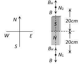
At neutral point
12. At a place the earth’s horizontal component of magnetic field is . If the angle of dip at that place is 60o, then the vertical component of earth’s field at that place in weber/m2 will be approximately
(A) (B) (C) (D)
Sol. D
From the relation
13. Obtain the earth’s magnetization. Assume that the earth’s field can be approximated by a giant bar magnet of magnetic moment 8.0 × 10²² A m2. The earth’s radius is 6400 km.
Sol. Intensity of magnetisation = = 72.89 A m–1
14. A bar magnet made of steel has a magnetic moment of 2.5 A m2 and a mass of 6.0 × 10⁻³ kg. If the density of steel is 7.9 × 10³ kg m–3, find the intensity of magnetisation of the magnet.
Sol.
15. A domain in ferromagnetic iron is the form of a cube of side length 1 μm. Estimate the number of iron atoms in the domain and the maximum possible dipole moment and magnetisation of the domain. The molecular mass of iron is 55 g/mole and its density is 7.9 g cm–3. Assume that each iron atom has a dipole moment of 9.27 × 10⁻²⁴ A m2.
Sol. Volume of cubic domain,
V = (10–6)3 m3 = 10–18 m3 = 10–12 cm3
Mass = Volume × Density = 7.9 × 10⁻¹² g
6.023 × 10²³ iron atoms has a mass of 55 g.
∴ Number of atoms in the domain,
The maximum possible dipole moment Mmax is achieved for the unrealistic case when all the atomic moments are perfectly aligned.
∴ Mmax = (8.65 × 1010) × (9.27 × 10–24) A m2
= 8.0 × 10⁻¹³ A m2
Corresponding magnetisation =
= 8.0 × 10⁵ A m–1
16. Moment of inertia of a magnetic needle is 40 gm-cm2 has time period 3 seconds in earth’s horizontal field = weber/m2. Its magnetic moment will be
(A) (B) (C) (D)
Sol. A
17. Magnets A and B are geometrically similar but the magnetic moment of A is twice that of B. If T1 and T2 be the time periods of the oscillation when their like poles and unlike poles are kept together respectively, then will be
(A) (B) (C) (D)
Sol. C