


1. INTRODUCTION
An electrical circuit consists of some active or passive elements. A battery or a cell supply, electrical energy to the circuit are the active elements. On the contrary, passive elements consume or store the electrical energy. Resistor, capacitor and inductor are the passive elements.
As charged particles move within a circuit, electric potential energy is transferred from a source to a device in which that energy is either stored or converted to another form, into sound in a stereo system or into heat and light in a toaster or light bulb. Electric circuits are useful because they allow energy to be transported without any moving parts.
2. ELECTRIC CURRENT
The free electrons present in the conductor are responsible for the flow of electric current. In a metallic conductor, on an average there will be one free electron available per atom. At any temperature, these free electrons will be moving in all direction at random. The electrons in the conductor are continuously making random collisions with the fixed atoms or ions inside the conductor. There collisions are inelastic in nature and result in transfer of energy. The resultant velocity will be zero in any direction. But when a potential difference is applied between the ends of conductor, an electric field E will act on these free electrons. As a result, an electron moves with an average velocity in a direction opposite to the field. This is called the drift velocity Vd and in of the order of 10–3 ms–1. All electrons will drift in the same direction. This drift is responsible for the flow of charge through the conductor.
Even though the electrons are responsible for the flow of current in a conductor, for simplicity and convenience and by convection, the current direction is the direction of positive charge motion. Current is not a vector quantity. It is a scalar because current doesn’t obey the law of vector addition.
In electrolytes or in gaseous conductors, the charge carries will be either positive or negative ions or both. In case of semiconductors the conduction is due to electrons and holes.
Current is defined as “the rate of flow of charge through any cross section of a conductor”. i.e., the net charge passing through any cross section of the conductor per unit time is the electric current (i).
If a net charge ‘q’ passes through any cross section of the conductor in time ‘t’, then the current ‘I’ is given by
I = q/t . . . . (1)
As q is in coulombs and ‘t’ is in seconds, ‘I’ will have the units of coulomb/sec.
In S.I. system, Ampere (A) is the unit of electric current.
Ampere
The current flowing through a conductor is said to be one ampere, if an amount of one coulomb of charge passes through any cross section of the conductor in one second.
It is macroscopic quantity like the mass of a body or volume of container. Current forms one of the fundamental physical quantities in S.I. system and is dimensionally denoted by [I] or [A].
Types of Current
According to its Magnitude and Directions Current is Usually Divided into Two Types:
(i) Direct current (DC) : If the magnitude and direction of current does not vary with time, it is said to be direct current (DC). Cell, battery or DC dynamo are its sources.
(ii) Alternating current (AC) : If a current is periodic (with constant amplitude) and has half cycle positive and half negative, it is said to be alternating current. AC dynamo is the source of it.
3. OHM’S LAW
The relationship between voltage across and current through a conductor was first discovered by German scientist George Simon Ohm. This relationship is called ohm’s law and may be state as under.
The potential difference across the ends of the conductor is proportional to the current (I) flowing through it provided the physical condition (like pressure, temperature, strain, etc) of the conductor remain unchanged.
i.e. V I
V = RI
where R is constant of proportionality and is known as electric resistance or resistance of the conductor.
Limitations of Ohm’s law
Ohm’s law is just an empirical relationship. It is not a fundamental physical principle and doesn’t specify any general property of matter. In case of electrolytes, another essential condition required for application of Ohm’s law is that the physical statements remain the same. But Ohm’s laws is obeyed fairly well by most of the metallic conductors. Ohm’s law is valid for metallic conductors in which V/i has a constant value irrespective of magnitudes of V and i.
But, even when V/i is not a constant, we can still define the resistance ‘R’ as
at every potential difference ‘V’ applied.
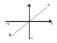
V-I characteristics
The variation of V and I through a conductor is shown in figure. It is represented by a straight line having a constant slope = . Higher slope of V-I curve means higher resistance. So OB represents higher resistance. Similarly I-V graph at different temperatures T1 and T2 is shown figure.

Resistance of a conductor
Resistance of a conductor is defined as the ratio of p.d. applied across its ends to the resulting current through the conductor’s i.e. .
Units of resistance is V/A or ohm (symbol ).
Dimensions of resistance is [ML2T-3A-2]
International ohm
It is defined as the resistance of 106.3 cm long mercury column of 1mm2 cross-sectional area and mass 14.4521 g at 0oC.
Factors upon which resistance depends:
The resistance R of a conductor
i) is directly proportional to its length i.e. R L
ii) is inversely proportional to its area of cross section, i.e. R 1/A.
iii) Depend upon the nature of the material.
iv) Changes with temperature.
From the first three points we have
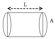
where is constant of proportionality and is known as resistivity or specific resistance of the conductor. Its value depends upon the nature of material and temperature.
SI unit of resistivity is ohm-m
The resistivity of metals and alloys is very small. Therefore, these materials are good conductors. On the other hand, resistivity of insulators is extremely large.
Conductance (G)
Conductance is defined as the reciprocal of the resistance of a conductor. The conductance of a conductor is the ratio of current ‘i’ to the voltage V.
Conductance,
or,
As R is in Ohm, the unit of G will be 1/ohm or mho. The S.I. unit of conductance is Siemens (s).
Conductivity ()
Conductivity is the measure of the ability of a material to conduct electric current through it. The conductivity of a material is defined as the reciprocal of its resistivity ().
i.e.,
The unit of conductivity are Siemens/meter or (ohm – m)–1.
4. MECHANISM OF CURRENT CONDUCTION IN METALS
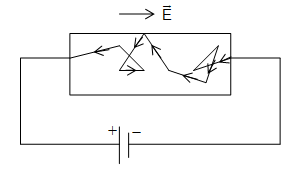
In a metal (conductor), free electrons move randomly with a thermal speed of the order of 105 m/s at room temperature. During random motion, the free electrons collide with positive ions (positive atom of metal) again and again and after each collision, their direction of motion changes. When we consider all the free electrons, their random motions average to zero. In other words, there is no net flow of charge in any particular direction.
When potential difference is applied across the end of a conductor as shown in figure;, electric field is applied at every point of the wire. The electric field exerts force on the free electrons which start accelerating towards the positive terminal (i.e. opposite to the direction of the field)
As the free electrons move they collide again and again with positive ions of the metal. Each collision destroys the extra velocity gained by the free electrons.
Relaxation time & Drift Velocity
The average time that an electron spends between two collisions is called the relaxation time.
Its value is of the order of 10-14 s.
Although, the free electrons are continuously accelerated by the electric field, collisions prevent their velocity from becoming large. The result is that electric field provides a small constant velocity towards +ve terminal which is superimposed on the random motion of the electron. This constant velocity is called the drift velocity.
The average velocity with which free electrons get drifted in a metallic conductor under the influence of electric field is called drift velocity .
Relation between electric field and drift velocity
Consider a metallic conductor connected to a battery as shown in figure.
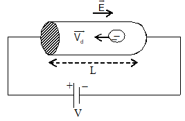
Let L=length of the conductor
V = p.d. across the conductor
m = mass of electron
e = charge on electron
= drift velocity of the free electrons.
= relaxation time
Magnitude of electric field E = .
Under the influence of electric field, each free electron experiences a force of –eE. The acceleration a of the electron is given by
since relaxation time is , the drift velocity of the free electron is given by
The negative sign shows that direction of drift velocity is opposite to the electric field.
Relation between current and drift velocity
Consider a conductor of length l and uniform cross-section area. Let V be the applied potential difference across ends of the conductor.
Let n = electron density (i.e. number of free electrons per unit volume)
Vd = drift velocity of free electrons
e = charge on each electron.
Total number of free electron in conductor = nAL
Total charge in the conductor (q) = nAl e . . . . . (i)
The time taken by the charge to cross the conductor length is given by t =
Current
. . . . . . (ii)
Electron mobility
The mobility of free electron is defined as the drift velocity of electron per unit electric field applied. It is denoted by e.
or Vd = eE
We can express electric current in terms of electron mobility.
Current density
Current density of a conductor is defined as the amount of current flowing per unit area of the conductor held perpendicular to the flow of current. It is denoted by (j). It is a vector quantity. The direction of the current density is the same as the direction of the current.
i.e.
we know, I = neAVd
The current dI through an element of surface area of a conductor is given by
Unit of current density is A/m2 (SI unit)
5. VALIDITY OF OHM’S LAW
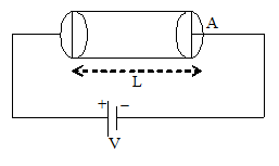
Consider a metallic wire of length L and uniform area of cross-section A. Let V be the applied p.d. across the end of the conductor and I the resulting current.

(only magnitudes)
We know that, I = neAvd
= neA .
The quantity is constant at a given temperature and given material. It is called resistivity ().
(for given conductors)
R is called resistance. This proves the validity of ohm’s law.
6. VARIATION OF RESISTIVITY WITH TEMPERATURE
We know that,
Here m is the mass of electron and e is charge on electron.
.
i.e. The resistivity depends upon the nature of conductor and not on its dimensions.
A. Metal
In case of metal, the value of n not change with temperature so that
……… (i)
If be the average distance converted by the electron between two successive collision and vrms be the root mean square speed that
As , hence vrms of free electrons increases with the rise in temperature.
Further as the temperature rises, the positive ions of metal vibrate with a higher amplitude and they obstruct more path of the free electrons. In other words decrease with raise in temperature. Consequently resistivity of the wire increase with rise in temperature.
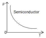
B. Semiconductor
In semiconductor, the value of n is very small compared to metal. When the temperature of a semiconductor increases, the value of n increases and that of decreases. But the increase in the value of n is greater than the decrease in the value of . The net result is that the resistivity of a semiconductor decreases with increases in temperature.
[In semiconductor, the temperature dependence of resistivity is given by
where K = Boltzmann constant (=1.38110-23 J molecule-1K-1)
T = Absolute temperature
Eg = Energy gap between conduction band and valence band]
C. Insulator
The resistivity of an insulator decreases exponentially with the rise in temperature.
7. TEMPERATURE DEPENDENCE OF RESISTIVITY AND RESISTANCE
The resistivity of all metallic conductors is found to increase with temperature, over a limited range of temperature (up to 1000C), the resistivity of metallic conductors is found to increase linearly with temperature. For higher temperature with the increase in temperature the ions of the conductor vibrate with greater amplitude and the collision between electrons and ions becomes more frequent.
If 0 is the resistivity of a material at temperature T0 and T is the resistivity of the same material at temperature T1 then,
The constant factor (alpha) is called the temperature coefficient of resistivity of the material.

Note: The reference temperature will be usually either 00C or 200C.
Here,
Thus, the temperature coefficient of activity may be defined as the fractional change in resistivity per unit rise in temperature.
Unit of are 0C–1 or oK–1.
Variation of resistivity () of a ohmic conductor with temperature T (Kelvin) will be shown in figure. Let us now consider some of the important details of the temperature dependence of resistivity.
(i) For certain metals at very lower temperatures, the temperature dependence of resistivity is quite non-linear. The graph will be curve.
(ii) Certain metallic alloys like Nickel, copper, chromium have high resistivity, because of it high resistivity, these are widely used in electric heaters.
(iii) Resistivity of Manganin (alloy of copper-nickel) is nearly independent of temperature. Manganin is widely used in making resistance boxes, standard resistances and wires used in metre bridge and potentiometer.
(iv) The resistivity of carbon decreases with increase of temperature and hence has a negative temperature coefficient of resistance. Semiconductors like germanium and silicon, also behave in the same way.
The resistance of a given conductor depends on its length and area of cross section besides the resistivity. As temperature changes, the length and area also change. But these change quite small and the factor may be treated as constant.
Then, R
Hence,
Where, R0 is the resistance at reference temperature T0 and RT is the resistance at temperature T.
8. OHMIC AND NON-OHMIC RESISTANCES (DEVICES)
Resistances that obey ohm’s law are called ohmic resistances. A metallic conductor at constant temperature is an ohmic resistance. For such ohmic resistances, the v-i characteristic curve will be straight line passing through the origin as shown in figure.
In ohmic resistances, current is reversed in direction when the P.D. is reversed, but magnitude of current remains same.
An electrolyte such as copper sulphate solution with copper electrodes, also obeys ohm’s law.
There are many resistances that do not obey ohm’s law. There are called non-ohmic resistances. For these resistances, the v – i characteristic curve will not be linear. The functioning of modern electronic devices is mainly based on these non-ohmic resistances (devices).
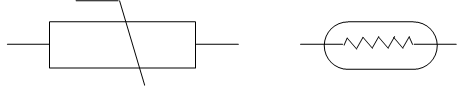
9. THERMISTOR
The temperature coefficient of resistivity is negative for semiconductors. This means that the resistivity decreases as we raise the temperature of such a material. The magnitude of the temperature coefficient of resistivity is often quite large for semiconducting material. This fact is used to construct thermometers to detect small changes in temperatures. Such a device is called thermistor. The variation of resistivity of a semiconductor with temperature is shown in figure.
A tiny bead of a semiconducting material forming the thermistor serves as a sensitive thermometer and can measure temperature charges of the order as smaller as 10–3K.
A thermistor is a heat sensitive and non-ohmic device. It is usually made of semiconductor compounds as the oxides of nickel, iron, cobalt, copper etc. The thermistor is usually enclosed in a capsule with an epoxy surface.
Thermistors are widely used in measuring the rate of energy flow in microwave beams. The beam falls on a thermistor and heat it. A relatively small rise in temperature results in very large change in resistance.
In a radio circuit, there will be several heater elements in series. A sudden and large surge of current through the circuit will damage the device. To prevent such a sudden surge of current, we place a thermistor with a high negative temperature coefficient of resistance, in series in the circuit. Initially the thermistor is in a relatively cold state and hence has a very high resistance. This prevent the current to a moderate level. Later, as the thermistor gets heated, its resistance decreases and it allows normal flow of current through the heater elements thereby preventing surge. A thermistor can also be used to serve as a thermostat.
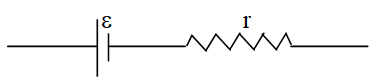
10. EMF, INTERNAL RESISTANCE & TERMINAL VOLTAGE
The Electromotive Force
For a continuous flow of current through a conductor AB of resistance ‘R’ we should always keep A at a positive (higher) potential and B at negative (lower) potential.
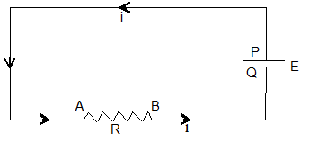
Through chemical action, the cell always maintain P at constant negative potential.
In the external circuit, current (+ve charge) flows from P to Q via the conductor AB. But inside the cell, the same positive charge has to move from a lower potential to higher potential. The must be able to do work on the charge. The energy to do this work is derived from the chemical process inside the cell.
The influence that makes current flow lower to higher potential (inside the battery) is called electromotive in taking a charge q from negative terminal to positive terminal, then work done by the battery per unit charged is called emf (E) of the battery.
Thus, E = T
The emf is measured in the units of Joule/coulomb (Jc–1) or volt.
“If the cell or battery does one Joule of work in driving one coulomb charge through the closed circuit connected to it, then emf of the cell is said to be one volt”.
Note: The resistance to flow of current inside the electrolyte solution of the cell is called the internal resistance of the cell. The emf and internal resistance of the cell will be fairly constant only when small current is drawn from the cell.
Internal Resistance of a Cell
The internal resistance of a cell is the resistance due to the electrolyte between the anode and cathode. The magnitude of the internal resistance depends on:
1) the distance between the plates
2) the area and size of the plates
3) Strength of the electrolyte and
4) temperature
Internal resistance decreases with increase of temperature. The internal resistance of a cell can be accurately measured with a potentiometer.
The difference between a new torch light cell and an old one is not in the emf. The decrease in emf will be very small. But, the difference is due to increase in internal resistance. After a prolonged use, the internal resistance increases by a factor 103.
Terminal Voltage (V)
When no current flows through the cell, the circuit is said to be an open circuit. This is shown in figure.
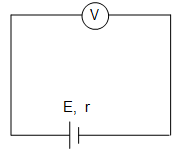
In such a case, the potential difference (P.D) across the terminals of the cell, called the terminal voltage (V) will be equal to the emf () of the cell. i.e., no current flows through the electrolyte and there is no potential drop across the internal resistance (r).
A voltmeter connected across the terminals of a cell in an open circuit reads the emf of the cell.
i.e., in an open circuit,
terminal voltage, V = emf = .
Now,
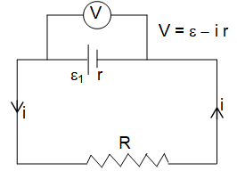
If an external resistance R is connected, across the two terminals of the cell, then current flows in the closed circuit, through both external resistance R and internal resistance r. If ‘I’ is the current in the circuit, we have,
and
or, = iR + ir = V + ir
Now, due to the current flow, there will be a potential drop in across the cell.
V = ir
For ideal cell, r = 0. Then , V =
Note : An ideal cell is only a concept and in practice it is not possible.
e.m.f. independents on (but P.D. depends on)
(i) resistance in the circuit
(ii) internal resistance of the cell and
(iii) current in the circuit
Note: Emf is cause but potential difference is effect.
Back emf
The terminal voltage across the terminals,
V = – ir
A part from this ‘ir’ drop there is also a decrease in the emf value on account of polarization, when current flows through the electrolyte solution, electrolysis takes place. This changes the composition of the cell. The copper electrode gets covered with a layer of hydrogen and this hinders flow of current. In the neighbourhood of both electrodes the concentrations of ions get altered. This results in an emf acting in a direction opposite to the emf of the cell, this is called back emf.
Note:
(i) Short circuiting: Two points in an electric circuit directly connected by a conducting wire are called short circuited under such condition both points are at same potential.
For example, resistance R1 in the adjoining circuits short circuited i.e. p.d. across it is zero. Hence no current how through R1 and the current flow through R2 is therefore .
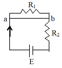
ii) Earthing: If some point of a circuit is earthed, then its potential is taken to be zero.
11. COMBINATION OF RESISTORS
In series
Figure represents a circuit consisting of a source of emf and three resistors connected in series. The equivalent resistor R would have the same resistance as the three resistors linked together.
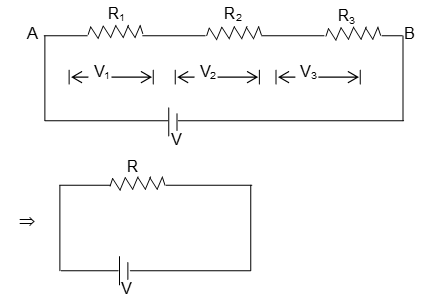
Because there is only one path for electric current to follows, i must have the same value everywhere in circuit. The P.D. between A and B is V.
This potential difference most somehow be divided into three parts V1, V2 and V3 as shown.
Then, V = V1 + V2 + V3
=
= or, . . . . (1)
Let R e the equivalent resistance between A and B then, V = iR . . . . (2)
From equations (1) and (2), we have,
R = R1 + R2 + R3 for resistors in series.
This results can be readily extended to a network consisting of a n resistors in series.
iR = R1 + R2 + ….. + Rni
In Parallel
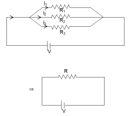
Figure represents a circuit consisting of a source of emf and three resistors connected in parallel. The current i however divides into three branches, which carry currents i1, i2 and i3.
i = i1 + i2 + i3 . . . . (3)
Let R be the equivalent resistance.
Here, (In parallel combination potential across resistance are same) Similarly,
Thom from equation. 3
or, for resistances in parallel.
This result can also be extended to a network consisting of a n resistors in parallel.
12. KIRCHHOFF’S LAWS
Ohm’s law is useful in the analysis of simple circuits containing a single source of emf and resistances in single branch. Just by computing equivalent resistances, we can calculate the currents. But, it is quite difficult and even impossible to calculate currents that flow in various branches of a complex circuit using Ohm’s law. To make it possible to find out the currents in different parts of such circuit Gustav Kirchhoff formulated two rules that are called Kirchhoff’s laws.
Kirchhoff’s first law applies to a junction and is also called “junction theorem”. The second law applies to a closed loop and is called “loop theorem”.
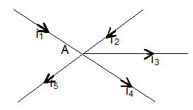
(i) Kirchhoff’s First Law (KCL)
Kirchhoff’s first law states that the sum of the currents flowing into junction is equal to the sum of the currents flowing out of the junction.
This law is a consequence of the low of conservation of charge. Electric charge is never accumulated at any point in a circuit.
This Law may also be stated as
“The algebraic sums of electric sum of electric currents at a junction in a circuit is zero.”
i.e.,
Note : The convection is to take currents flowing into a junction as positive and currents flowing out as negative.
(ii) Kirchhoff’s Second Law
Kirchhoff’s second law states that the sum of the potential drops around the loop is equal to the sum of potential drops around the loop.
This law is a consequence of the law of conservation of energy.
Kirchhoff’s second law may also be stated as:
“In any closed circuit, the algebraic sum of all the potential difference is zero.”
When we travel through a source in the direction from – to +, the e.m.f. is considered to be positive, when we travel from +ve to -ve, the emf is considered to be negative.
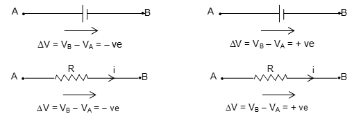
When we travel through a resistor in the same direction as the assumed current, the ‘iR’ term is negative because the current goes in the direction of decreasing potential. When we travel through a resistor in the direction opposite to the assumed current, the iR term in positive because this represents a rise of potential.
13. APPLICATIONS OF KIRCHHOFF’S LAWS
Wheat Stone Bridge
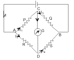
Wheat stone bridge is an electric circuit used to compare the resistances or find the value of an unknown resistance. It consists of four resistances, a battery and a galvanometer. When no current flows through the galvanometer the bridge is said to be balanced.
In a wheat stone bridge, four resistances, P, Q, R and S are joined to form the four sides of quadrilateral as shown in figure. These four sides are referred to as arms of the bridge. Four junctions are formed at A, B, C and D.A battery of emf is connected between the two junction A and B. A galvanometer G of resistance G ohm is connected between the other two junctions C and D.
The galvanometer gets deflected whenever a current passes through it. It shows zero or null deflection, when no current passes through it. The distribution of the original current ‘I’ among the various branches of the circuit as shown in the figure. Applying the Kirchhoff’s first law (KCL). We get at junction C,
i1 = ig + i3 . . . . (1)
at junction D,
i2 + Ig = I4 . . . . (2)
Applying the Kirchhoff’s second law, for the loop ACDA, with currents in clockwise direction taken as positive.
i1 P + ig G – i2 R = 0 . . . . (3)
and for the loop CBDC, again with currents in clockwise direction taken as positive.
i3 Q – i4 S – ig G = 0 . . . . (4)
For the bridge to be balanced, no current should pass through galvanometer in any direction.
i.e., ig = 0 . . . . (5)
Now, i1 P – i2 R = 0
or, i1 P = i2R . . . . (6)
and i3 Q – i4 S = 0
or, i3 Q = i4 S . . . . (7)
diving equations (6) by (7), we have, (using equation (1) and (2)
This is the balancing condition for wheatstone bridge and is called the wheatstone bridge principle.
Note: On interchanging the position of cell and galvanometer the balancing condition is not altered.
Uses of a Wheat Stone Bridge
(i) We can compare unknown resistances Q and S from .
(ii) The small strains produced in hard materials can be measured accurately with a wheatstone bridge using a strain gauge. (A strain gauge is a small, flat coil of wire that is finally attached to the material under strain. The strain produced gives rise to a change in resistance of the coil, which can be measured with the Wheatstone bridge. From this, the strain can be calculated.
(iii) Instead of with resistances, we can form a D.C. Wheatstone bridge with four capacitors of capacitors C1, C2, C3 and C4. The balancing condition, will be
Metre Bridge
The working of a meter bridge is based on the principle of wheat stone bridge. It is a simpler form of wheat stone bridge and is more accurate because, the resistances R and S can be changes in continuous fashion. It is called a metre bridge because it consists of wire AB of one metre length.
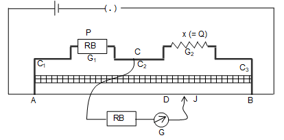
The metre bridge is shown in figure consists of three thick stripes C1, C2 and C3 made of copper or brass. The resistances of these stripes are almost zero. The shapes and positions of strips fixed on a wooden board are as shown in figure. A manganin wire of uniform cross section and 1m length is stretched tight between the two terminals A and B. A jockey ‘J’ slides over the wire. A metre scale S is fixed by the side of the wire for taking the lengths of the wire. The lengths are to be measured from the end where metre terminal of battery is connected at A in figure. A battery of emf ‘’ a plug key are connected between the two terminals A and B. A resistance box ‘RB’ is connected in the gap ‘G1’. The unknown resistance ‘X’ is connected in gap ‘G2’. In between the centre C of strip C2 and the Jocky ‘J’ a galvanometer G and high resistance ‘HR’ are connected in series. When the Jockey is at point ‘D’ on the wire, it divides the wire into two parts AD and DB of lengths l1 and l2.
As the wire is of uniform cross section, we can have resistance of AD of length of wire = R = l1 and Resistance of DB length of wire = S = l2 ,
Where is the resistance per unit length of the wire. Now, the circuit is similar to a wheat stone bridge with resistance in RB = P.
Here, unknown resistance, X = Q
When the bridge is balanced, we have,
But in a metre bridge, l2 = (100 – l1)
So, the balanced condition of a metre bridge is
Experimental procedure:
A suitable value of resistance P is kept in the resistance box. In the beginning, the high resistance (HR) is included in series with the galvanometers in the circuit. The connections are checked for deflections in galvanometer by pressing the jockey first near A and then at B.
If these deflections are in opposite directions, the connection is proper. Otherwise the connections are to be checked. The Jockey is now pressed at various points, the wire from A to towards ‘B’, until we get near null deflection in the galvanometer. At this stage, the high resistance is shunted (removed) and the exact balance point giving null deflection at D is obtained. The length l1 from A to D is noted, the unknown resistance X can be calculated.
Specific resistance (Resistivity) of the material of a given wire can also be determined using metre bridge, we keep the given wire in gap ‘G2’ and determine its resistance (r) as described above. Then length of the wire (L) and radius of cross section (r) are measured. The specific resistance of the material of the wire () is calculated from,
Precautions
The following precautions are to be observed with a metre bridge experiment:
(i) The current must be kept at a low value. Otherwise, resistance of wire are getting heated and affects the values.
(ii) The current should not be passed continuously for a very long time. The wire gets heated and values will be altered.
(iii) The Jockey should not be dragged along the wire, otherwise, the wire gets deformed and its resistance gets altered.
Importance of high resistance:
The galvanometer is a very resistive current meter. It should be protected from high currents flowing through it. For this reason, a high resistance is included in series with the galvanometer, when the balancing point is not obtained, because of HR in series, the current through galvanometer will be very small. But, when the near balance is obtained, the H.R. is be removed for getting an accurate value for balancing length. Now, there will be no damage to galvanometer, because already near balance is achieved and current through galvanometer will be very small.
Uses of Metre Bridge:
1. Determine an unknown resistance
2. Compare two resistances
3. Determine the specific resistance of the material of a wire.
Potentiometer
A uniform wire of manganin 4.6 or 10 metre long is fixed on a wooden plank. Generally, separate pieces of wire, each one metre long are fixed parallel to each other besides a metre scale on the wooden plank. The wires are joined to each other by thick copper strips of negligible resistance so that the combination acts as a single wire of the required length as shown in fig.
The ends of the potentiometer wire AB are connected to a standard cell of emf E or a source of emf E that supplies constant current. The current through the potentiometer wire can be varied by means of a series resistance RS which is adjustable.
Let r be the internal resistance of the cell of emf E connected across the potentiometer wire of length L and resistance R. The current through the potentiometer wire is
The potential of the wire decreases from the end A to the end B. The potential fall or potential drop across a length l of the potentiometer wire is
V = Current x Resistance of length l of the potentiometer wire =
Since the resistance of a uniform wire is proportional to its length, for the total length L of the potentiometer wire the resistance is R i.e., resistance per unit length of the wire is R/L and the resistance of the wire of length l is (R/L)l.
If the resistance per unit length of the wire, R/L is denoted by , the potential drop across the wire is V = Il
The potential difference across a length of the potentiometer wire is directly proportional to its length (provided the current through the wire and the resistance per unit length are constant.) This is the principle of the potentiometer.
is called potential drop per unit length of the potentiometer wire or potential gradient of the wire. It is given by
The sensitivity of a potentiometer is related to its potential gradient. Similar the potential gradient greater will be the sensitivity of potentiometer. The increase the sensitivity of a potentiometer, the potential gradient, is to be made smaller. This is possible if (i) the length of the potentiometer, L is larger and (ii) series resistance, R is larger. The circuit that provides constant current to the potentiometer wire is called primary circuit. Potentiometer can be used i) to compare emfs of two cells, ii) to determine the internal resistance of a cell, iii) to calibrate an ammeter and voltmeter iv) to measure very small emfs like thermo emfs etc.
Potentiometer is an instrument which can measure accurately
Application of potentiometer
(i) To determine the internal resistance of a primary cell
(ii) Comparison of emfs of two cell:
(iii) Comparison of resistances:
Grouping of Cells
(i) Series grouping: In series grouping anode of one cell is connected to cathode of other cell and so on. If n identical cells are connected in series.
Equivalent emf of the combination Eeq = nE
Equivalent internal resistance req = nr
Current from each cell =
Condition from max. power and power dissipated in the external circuit = , then maximum power =
(ii) Parallel grouping: In parallel grouping all anodes are connected at one point and all cathode are connected together at other point. If n identical cells are connected in parallel.
Equivalent emf Eeq = E
Equivalent internal resistance req = r/n
Current i =
Condition from max. power R = r/n and power dissipated in the external circuit = , then maximum power =
HEATING EFFECT OF ELECTRIC CURRENT
14. JOULES HEATING
When some potential difference V is applied across a resistance R then the work done by the electric field on charge q to flow through the circuit in time t will be W = qV = Vit = i2Rt = . This work appears as thermal energy in the resistor.
Heat produced by the resistance R is . This relation is called joules heating.
15. ELECTRIC POWER
The rate at which electrical energy is dissipated into other forms of energy is called electrical power i.e.
1. Units: It’s S.I. unit is Joule/sec or Watt
Bigger S.I. units are KW, MW and HP, remember 1 HP = 746 Watt
2. Rated values: On electrical appliances (Bulbs, Heater, Geyser …. etc.). Wattage, voltage, ……. etc. are printed called rated values e.g. If suppose we have a bulb of 40 W, 220 V then rated power (PR) = 40 W while rated voltage (VR) = 220 V.
3. Resistance of electrical appliance: If variation of resistance with temperature is neglected then resistance of any electrical appliance can be calculated by rated power and rated voltage i.e. by using .
4. Power consumed (illumination) : An electrical appliance (Bulb, heater, …. etc.) consume rated power (PR) only if applied voltage (VA) is equal to rated voltage (VR) i.e. If VA = VR so Pconsumed = PR. If VA < VR then also we have so
5. Long distance power transmission: When power is transmitted through a power line of resistance R, power-loss will be
Now if the power P is transmitted at voltage V then P = Vi i.e. i = (P/V). So,
Now as for a given power and line, P and R are constant so
So if power is transmitted at high voltage, power loss will be small and vice-versa. This is why long distance power transmission is carried out at high voltage.
16. ELECTRICITY CONSUMPTION
1. The price of electricity consumed is calculated on the basis of electrical energy and not on the basis of electrical power.
2. The unit Joule for energy is very small hence a big practical unit is considered known as kilowatt hour (KWH) or board of trade unit (B.T.U.) or simple unit.
3. 1 KWH or 1 unit is the quantity of electrical energy which dissipates in one hour in an electrical circuit when the electrical power in the circuit is 1 KW thus 1 KWH = 1000 W 3600 sec = 3.6 106 J.
4. Important formulae to calculate the no. of consumed units is
17. COMBINATION OF BULBS
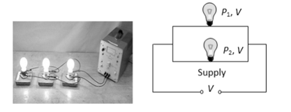
1. Series combination
(i) Total power consumed
(ii) If ‘n’ bulbs are identical,
(iii) i.e. in series combination bulb of lesser wattage will give more bright light and p.d. appeared across it will be more.
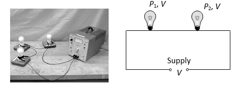
2. Parallel combination
(i) Total power consumed
(ii) If ‘n’ identical bulbs are in parallel.
(iii) i.e. in parallel combination, bulb of greater wattage will give more bright light and more current will pass through it.
SOLVED EXAMPLES
1. The current in a wire varies with time according to the relation.
I = (3.0A) + (6.0 A/S)t
a) How many coulombs of charge pass a cross-section of the wire in the time internal between t = 0 and t = 4.0s?
b) What constant current would transport the same charge in the same time interval?
Sol.
a)
or,
or,
b)
2. A curve of length 2m and diameter 0.4mm has a resistance of 200 . Calculate the specific resistance of the material of the wire.
Sol. Length of the wire, l = 2m
And resistance of the wire, R = 200
radius of the wire,
Then, area of cross section of the wire, A = r2
or,
The specific resistance or resistivity of the wire,
= 1.256 10–5 .m
3. A copper wire of diameter 1 cm has a resistance of 0.15. It is drawn under pressure so that its diameter is reduced to 50%. What is the new resistance of the wire?
Sol. Given d1 = 1cm, d2 = ,
R1 = 0.15 .
Let initial length of the wire is l1 and final length l2.
As the volume of the wire is remain same before and after drawing.
A1l1 A2l2 .
We know
R2 = 16R1 = 160.15 = 2.4 .
4. Two wires of aluminium and copper have the same resistance and same length which of them is lighter? Given that dCu = 8.9103 kg/m3, dal = 2.7103 kg/m3,
cu = 1.7210-8 m, Al=2.610-8 m.
Sol. Given that Ral = Rcu
……… (1)
Now,
It is clear that, for same length and resistance, a aluminium wire is lighter than copper wire.
5. A copper wire of area of x-section 4 mm2 is 4 m long and carries a current of 10A. The number density of free electrons is 81028 /m3. How much time is required by an electron to travel the length of wire?
Sol. I = 10A, a = 4 mm2 = 410-6 m2, L = 4m, e=1.610-19C, n=81028 m-3.
We know,
6. A copper wire of area of x-section 10-7 m2 is carrying a current of 1.5A. Assuming that each copper atom contributes one conduction electron, calculate (i) Current density in the wire and (ii) The drift velocity of electrons. Given that (Cu = 9103 kg/m3A atomic mass is 63.5.
Sol. Given that A = 10-7 m2, I = 1.5A
a) Current density
b) Density of conduction electrons
7. A copper conductor has a resistance 2.5 at a temperature of 250C and 2.9 at 750C. Calculate the temperature coefficient of resistivity of copper and also the resistance of the conductor at 00C.
Sol. The resistance of the conductor is R0 = 2.5
at a temperature, T0 = 250C
The resistance of the conductor is RT = 2.8
at a temperature, T = 750C
a) If is the temperature coefficient of resistivity of copper
we have, 2.8 = 2.5 [1 + (75 – 25)]
= 2.5 [1 + .50]
or, 1 + 50 =
or, 50 = 0.12
Temperature coefficient of resistivity,
= 2.4 10–3 (oC)–1
b) at 00C
= 2.35
8. For what value of E, the potential of A is equal to the potential of B?
Sol. Both the cells are additive in nature.
Hence, current in the circuit will be,
Potential of A is equal to the potential of B.
i.e., VAB = 0 or E – ir = 0
Solving this equation, we get E = 5 volt.
9. In the circuit shown in figure.
E1 = 10V. E2 = 4V
r1 = r2 = 1 and R = 2

Find the potential difference across cell 1 and cell 2.
Sol. Net emf of the circuit = E1 – E2 = 6V
Total resistance of the circuit = R + r1 + r2
= 4
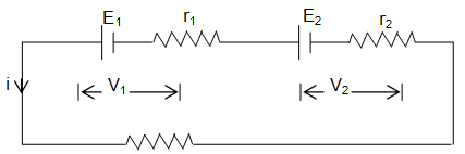
current in the circuit i =
Now,
= 8.5 volt
and, V2 = E2 + ir2 = 4 + (1.5) (1) = 5.5 volt
10. Four resistances each of 100 are connected in the form of a square. Determine the effective resistance along P and Q.
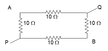
Sol. From the figure,
Resistance between PA and AQ are in series,
Then,
Similarly, resistance between PB and BQ are in series,
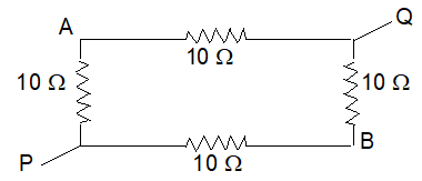
Now, are in parallel.
Then,
=
or,
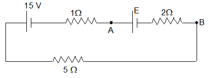
11. In figure, find the current in each resister and the potential difference between points a and b. Put E1 = 6.0V, E2 = 5.0V, E3 = 4.0V, R1 = 100 and R2 = 50.
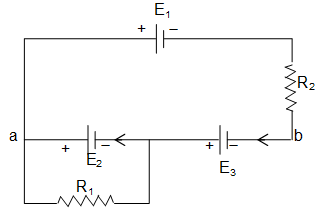
Sol. Let i1 and i2 are the currents flowing through resistors R1 and R2.
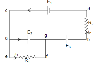
Using KVL, (loop rule)
For loop cabdc,
or,
and for loop aefga.,
-i1R1 + E2 = 0
or,
Now, the P.D. between point a and b,
= 9 V
12. Calculate the currents in the two resistance shown in the given figure.

Sol. Applying Kirchhoff’s loop law to the closed loop ABCDA
2I + 1.5 + 3I – 3 = 0
5I – 1.5 = 0
I = 0.3A.
13. Obtain the total resistance between the terminal A and B of the given network.
Sol. Distribution of current in circuit is shown in figure.
Applying kirchhoff’s loop law to the closed loop ACDA
…………. (i)
Applying kirchhoff’s loop law to the closed loop CBDC
……………(ii)
Put I1 value in equation (i)
2(12I2 – 5I) – 3I2 = 2I
24I2 – 3I2 = 12I
I2 =
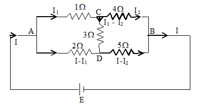
From equation (ii) I1 =
Let equivalent resistance between A & B is R
VA – VB = R I = I1 + 4I2
RI =
14. Two parallel resistances 4 and 8 are connected with a known resistance of 6 as shown in figure, where as the balance point on the wire of the metre bridge?
Sol. Here R = 6,
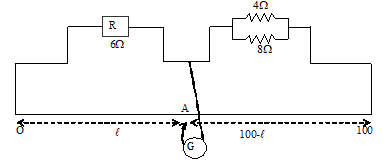
Let the balance point be at A on the wire at a distance l from O.
Now
or
900 = 13l
15. AB is a uniform wire of 10 resistance. The other data are as shown in the circuit diagram given below. Calculate (a) potential gradient along AB. (b) length AO of the wire, when the galvanometer shows no deflection.
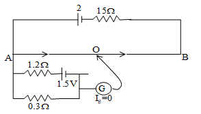
Sol. Since, the galvanometer shows no deflection so current in wire AB
Potential gradient =
Potential difference across AO =
Length AO =
16. In household wiring, copper wire 2.05 mm in diameter is often used. Find the resistance of a 35.0m long wire. Specific resistance of copper is 1.72 10–8 – m.
Sol. We known that,
Resistance of the wire,
Here, = 1.72 10–8 – m, l = 35.0 m and
Then, substituting the values, we have,
17. A wire carries a current of 1 A. (a) How much charge flows through the wire in 5.0 minutes? (b) How many electrons will cross over a particular point in the conductor during this period?
Sol: Current flows through the wire = i = 1A.
and time of current flow = t = 5 minutes
= 5 60 = 300s.
(a) Let the charge flowing through the wire in this time be q.
form, we have,
q = i.t = (1A) (300 S)
= 300 C . . . (1)
(b) Let the number of electrons crossing over a particular point be n.
we know that,
q = n (1.6 10–19C) . . . . (2)
from equation (i) and (ii), we have,
or,
18. An aluminium wire carrying a current has diameter 0.84 mm, the electric field in the wire is 0.49 V/m. What is (a) the current carried by the wire? (b) the potential difference between two points in the wire 12.0m apart? (c) the resistance of a 12.0m length of this wire? Specific resistance of aluminium
= 2.75 10–8 -m.
Sol. (a) We know that,
Current carried by the wire,
i.e.,
=
Substituting the values, we have,
(b) Potential difference, V = E.l
= (0.49 v/m) (12 m)
= 5.9 volt.
19. Two wires of the same material and having lengths in the ratio of 2 : 3 are connected in series. The p.d. across the wires are 4.2v and 3.6v respectively. Compare their radii.
Sol. Let l1 and l2 be the lengths of the wires,
r1 and r2 be the radii of the wires,
V1 and V2 be the p.d. across the wires,
i1 and i2 be the current through the wires and
R1 and R2 be the resistances of the wire respectively.
Given,
But, V1 = i2R1 and V2 = i2R2 and as the two wires are in series, current will be the same, i.e., i1 = i2 . . . . (1)
Again,
and,
Hence, . . . . (2)
As, the two wires are made of the same material, 1 = 2 and,
. . . . (3)
From (1) and (3), we have,
or,
Ratio of the radii of the wire is
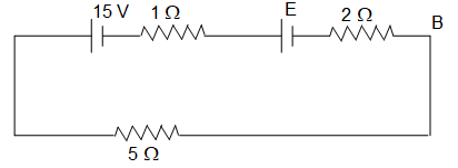
20. For what value of E the potential of point A is equal to the potential of point B?
Sol. Both the batteries are additive in nature.
Hence, current in the circuit will be
potential of point A is given equal to the potential of point B.
i.e., VA = VB
Then, VAB = VA – VB = 0
or, E – ir = 0 (here, r = 2 )
or, E – E – 15 = 0
or, E = 5 volt.
21. A battery when connected by a resistance of 16 gives a terminal voltage of 12volt and when connected by a resistance of 10 gives a terminal voltage of 11volt. Calculate the emf of the battery and its internal resistance.
Sol. Let the emf of the battery be internal resistance r and terminal voltage be V. When an external resistance R is connected.
Then, the current is given by,
. . . . (1)
In the first cane, R = 16 and V = 12volt (given)
or, . . . . (2)
In the second case, R = 1
or and V = 11volt (given)
. . . . (3)
from (2) and (3), we have,
or, r = 2.857
Substituting value of r in (2), we get
= 14.14volt.
Thus, the emf of the battery, = 14.14volt, and internal resistance, r = 2.857
22. Determine the values of currents i1, i2 and i3 shown in given figure.
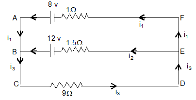
Sol. Given, 1 = 8volt, r1 = 1
2 = 12volt, r2 = 1.5
and R = 9
Applying Kirchhoff’s first law at the junction B, we have
i1 + i2 = i3 . . . . (1)
Applying Kirchhoff’s second law to loop ABEFA, have we are taking current is anticlockwise direction is positive.
(i1 1) – (i2 1.5) = 8 – 12
or, i1 – 1.5 i2 = – 4
or, 1.5i2 – i1 = 4 . . . . (2)
From loop BCDEB, (i2 1.5) + (i3 9) = 12
or 1.5i2 + 9i3 = 12 . . . . (3)
from equation (1) and (2), we have 1.5i2 + 9i1 + 9i2 = 12
or, 9i1 + 10.5i2 = 12 . . . . (4)
Now, equation (2) 9 gives
9i1 – 13.5i2 = – 36 . . . . (5)
Subtracting equation (5) from equation (4), we have
i2 = 2A
then, i1 = – 1A and i3 = 1A
Here, i1 = – 1A i.e. the current i1, flows in the direction of BAFE.
23. The potentiometer wire AB is 600 cm long.
(a) At what distance from A should the Jockey J touches the wire to get zero deflection in the galvanometer?
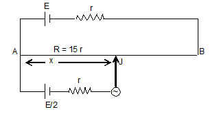
(b) If the Jockey touches the wire at a distance 560 cm from A. What will be the current through the galvanometer?
Sol. (a) In case of zero deflection in galvanometer,
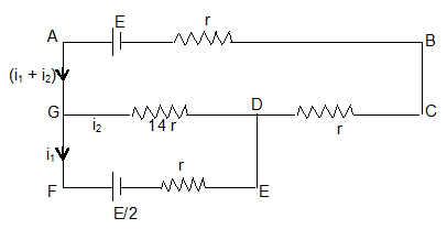
or,
or, x = 320 cm
(b) In this case,
The circuit can be drawn as under,
Applying second law in loop ABCDGA, we have,
-E + (i1 + i2) r + (i1 + i2)r + 14i2 r = 0 . . . . (1)
Further applying second law in loop is DEFG, we have
– 14r i2 r + i1r + . . . . (2)
Solving these two equations, we get,
24. Two unknown resistances x and y are connected to the left and right gaps of a meter bridge. Its balance point is at 50cm. When a resistance of 20 is connected in series with x, the balance point is at 60cm. Calculate x and y.
Sol. Given, l1 = 50cm with x
and l2 = (100 – 50) = 50 cm with y,
. . . . (1)
When, 20 is in series with x, the effective resistance is (x + 20) and now,
l1 = 60cm and l2 = 40cm
Then, . . . . (2)
(1) divided by (2), given
or,
or, 3x = 2x + 40
or, x = 40
x = y = 40
25. Find the emf and internal resistance of a single battery which is equivalent to a combination of three batteries as shown in figure.
Sol. The given combination consists of two batteries in parallel and resultant of these two in series with the third one.
For parallel combination we can apply,
Eeq.=
and,
Now, this is in series with third one,
Then, the equivalent emf of these two is,
E = (6 – 3) volt = 3volt
and, the internal resistance will be, r = (1 + 1) = 2
26. An electric motor operating on 50 volts DC supply draws a current of 10 amp. If the efficiency of the motor is 40%, calculate the resistance of the winding of the motor.
Sol. Given that V = 50 volt, I = 10A, = 40%
Input power, Pi = VI = 50 10 = 500 W
Let resistance of the winding of the motor is R
Power consume by motor = I2 R = (10)2R = 100R
Output power = Pi – power consume by motor
Po = 500 – 100R
200 = 500 – 100R
100R = 300 R = 3
27. An electric bulb is marked 100V, 230W. It the supply voltage drops to 115V, what is the heat and light energy produced by the bulb in 20 min.
Sol. Given that, P = 100 W, V = 230V,
Supply voltage Vs = 115V
Now
When the voltage drop to 115V, heat and light energy produced by the bulb in 20 minutes is H =
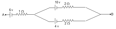
28. An electric power station (100 MW) transmits power to a distant load through long and thin cables. Which of the two modes of transmission would result in lesser power wastage for power transmission at (i) 20,000 V or (ii) 200 V?
Sol. Given that P = 100 MW = 100 106 W
V1 = 20,000V, V2 = 200 V
In first case, when the transmission is done at 20,000 volt, the current through the cables is
similarly, current in the 2nd case
Let R be the resistance of the cables. Then loss of power in transmission
In the first case =
In the second case =
Hence, there would be lesser power wastage in the first mode of transmission.
29. Two bulbs rated at 25 watts, 110 volts, 100 watts 100 volts are connected in series to a 220V electric supply. Perform the necessary calculations to find out which of the two bulbs, if any will fuse. What would happen if the two bulbs were connected in parallel to the same supply?
Sol: From the rating printed on the bulbs
P1=25W, P2=100W
V1=V2 = 110 V
since the both bulbs are connected in series
supply voltage = 200
Current flow through the circuit
P.D. across 1st bulb = I R1 =
P.D. across 2nd bulb =
Since P.D. across 1st bulb is greater than rating voltage 110V
Hence the first bulb will fuse
When both bulbs connected in parallel
Since the supply voltage is greater than rating voltage of both bulbs, both the bulbs will fuse in this case.