


Thermodynamics is a branch of science which deals with exchange of heat energy between bodies and conversion of the heat energy into mechanical energy and vice-versa.
1. SOME DEFINITIONS
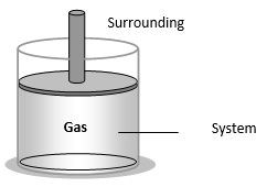
Thermodynamic system
(i) It is a collection of an extremely large number of atoms or molecules
(ii) It is confined within certain boundaries.
(iii) Anything outside the thermodynamic system to which energy or matter is exchanged is called its surroundings.
(iv) Thermodynamic system may be of three types
(a) Open system: It exchange both energy and matter with the surrounding.
(b) Closed system: It exchange only energy (not matter) with the surroundings.
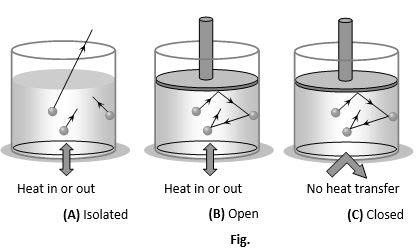
(c) Isolated system: It exchange neither energy nor matter with the surrounding.
Thermodynamic variables and equation of state
A thermodynamic system can be described by specifying its pressure, volume, temperature, internal energy and the number of moles. These parameters are called thermodynamic variables. The relation between the thermodynamic variables (P, V, T) of the system is called equation of state.
For moles of an ideal gas, equation of state is PV = RT and for 1 mole of an it ideal gas is PV = RT
Thermodynamic equilibrium
In steady state thermodynamic variables are independent of time and the system is said to be in the state of thermodynamic equilibrium. For a system to be in thermodynamic equilibrium, the following conditions must be fulfilled.
(i) Mechanical equilibrium: There is no unbalanced force between the system and its surroundings.
(ii) Thermal equilibrium: There is a uniform temperature in all parts of the system and is same as that of surrounding.
(iii) Chemical equilibrium: There is a uniform chemical composition throughout the system and the surrounding.
Thermodynamic process
The process of change of state of a system involves change of thermodynamic variables such as pressure P, volume V and temperature T of the system. The process is known as thermodynamic process. Some important processes are
(i) Isothermal process: Temperature remain constant
(ii) Adiabatic process: No transfer of heat
(iii) Isobaric process: Pressure remains constant
(iv) Isochoric (isovolumetric process): Volume remains constant
(v) Cyclic and non-cyclic process: In cyclic process Initial and final states are same while in non-cyclic process these states are different.
(vi) Reversible and irreversible process:
Indicator diagram
Whenever the state of a gas (P, V, T) is changed, we say the gaseous system is undergone a thermodynamic process. The graphical representation of the change in state of a gas by a thermodynamic process is called indicator diagram. Indicator diagram is plotted generally in pressure and volume of gas.
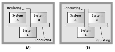
2. ZEROTH LAW OF THERMODYNAMICS
If systems A and B are each in thermal equilibrium with a third system C, then A and B are in thermal equilibrium with each other.
(1) The zeroth law leads to the concept of temperature. All bodies in thermal equilibrium must have a common property which has the same value for all of them. This property is called the temperature.
(2) The zeroth law came to light long after the first and seconds laws of thermodynamics had been discovered and numbered. It is so named because it logically precedes the first and second laws of thermodynamics.
3. HEAT, INTERNAL ENERGY AND WORK IN THERMODYNAMICS
Heat (ΔQ)
It is the energy that is transferred between a system and its environment because of the temperature difference between them.
(i) Heat is a path dependent quantity e.g. Heat required to change the temperature of a given gas at a constant pressure is different from that required to change the temperature of same gas through same amount at constant volume.
(ii) For gases when heat is absorbed and temperature changes
At constant pressure
At constant volume
Internal energy (U)
Internal energy of a system is the energy possessed by the system due to molecular motion and molecular configuration.
The energy due to molecular motion is called internal kinetic energy UK and that due to molecular configuration is called internal potential energy UP i.e. Total internal energy U = UK + UP
(i) For an ideal gas, as there is no molecular attraction UP = 0
i.e. internal energy of an ideal gas is totally kinetic and is given by and change in internal energy
(ii) In case of gases whatever be the process
(iii) Change in internal energy does not depend on the path of the process. So it is called a point function i.e. it depends only on the initial and final states of the system, i.e.
Work (ΔW)
Suppose a gas is confined in a cylinder that has a movable piston at one end. If P be the pressure of the gas in the cylinder, then force exerted by the gas on the piston of the cylinder F = PA (A = Area of cross-section of piston)
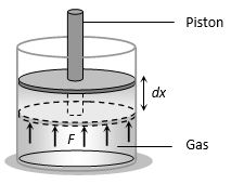
When the piston is pushed outward an infinitesimal distance dx, the work done by the gas
For a finite change in volume from Vi to Vf
Total amount of work done
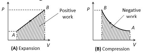
(i) If we draw indicator diagram, the area bounded by PV-graph and volume axis represents the work done
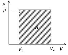
Work = Area = P(V2 – V1)
Work =
Work = 0
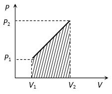
Work = Area of the shown trapezium
(ii) From
If system expands against some external force then
W = positive
If system contracts because of external force then
W = negative
(iii) Like heat, work done is also depends upon initial and final state of the system and path adopted for the process
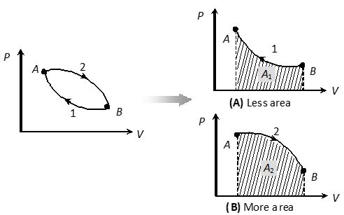
A1 < A2 W1 < W2
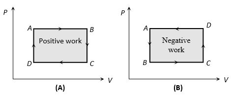
(iv) In cyclic process, work done is equal to the area of closed curve. It is positive if the cycle is clockwise and it is negative if the cycle is anticlockwise.

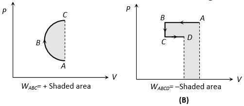
Work = Area of triangle ABC
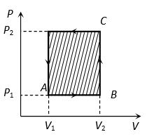
Work = Area of rectangle ABCD
= AB AD
= (V2 – V1) (P2 – P1)

Work =
4. FIRST LAW OF THERMODYNAMICS
(1) It is a statement of conservation of energy in thermodynamical process.
(2) According to it heat given to a system (ΔQ) is equal to the sum of increase in its internal energy (ΔU) and the work done (ΔW) by the system against the surroundings.
ΔQ = ΔU + ΔW
(3) It makes no distinction between work and heat as according to it the internal energy (and hence temperature) of a system may be increased either by adding heat to it or doing work on it or both.
(4) ΔQ and ΔW are the path functions but ΔU is the point function.
(5) In the above equation all three quantities ΔQ, ΔU and ΔW must be expressed either in Joule or in calorie.
(6) The first law introduces the concept of internal energy.
(7) Limitation: First law of thermodynamics does not indicate the direction of heat transfer. It does not tell anything about the conditions, under which heat can be transformed into work and also it does not indicate as to why the whole of heat energy cannot be converted into mechanical work continuously.
Useful sign convention in thermodynamics
| Quantity | Sign | Condition |
| ΔQ | + | When heat is supplied to a system |
| – | When heat is drawn from the system | |
| ΔW | + | When work done by the gas (expansion) |
| – | When work done on the gas (compression) | |
| ΔU | + | With temperature rise, internal energy increases |
| – | With temperature fall, internal energy decreases |
5. ISOBARIC PROCESS
When a thermodynamic system undergoes a physical change in such a way that its pressure remains constant, then the change is known as isobaric process.
(1) Equation of state: In this process V and T changes but P remains constant. Hence Charles’s law is obeyed in this process.
Hence if pressure remains constant V T
(2) Indicator diagram: Graph 1 represent isobaric expansion, graph 2 represent isobaric compression.
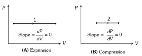
(i) In isobaric expansion (Heating)
Temperature increases so ΔU is positive
Volume increases so ΔW is positive
Heat flows into the system so ΔQ is positive
(ii) In isobaric compression (Cooling)
Temperature decreases so ΔU is negative
Volume decreases so ΔW is negative
Heat flows out from the system so ΔQ is negative
(3) Specific heat: Specific heat of gas during isobaric process
(4) Bulk modulus of elasticity:
(5) Work done in isobaric process
[As P = constant]
(6) FLOT in isobaric process: From
(7) Examples of isobaric process: All state changes occurs at constant temperature and pressure.
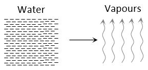
Boiling of water
(i) Water vapours
(ii) Temperature constant
(iii) Volume increases
(iv) A part of heat supplied is used to change volume (expansion) against external pressure and remaining part is used to increase it’s potential energy (kinetic energy remains constant)
(v) From FLOT ΔQ = ΔU + ΔW mL = ΔU + P(Vf – Vi)
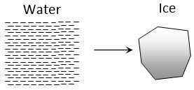
Freezing of water
(i) Water ice
(ii) Temperature constant
(iii) Volume increases
(iv) Heat is given by water it self. It is used to do work against external atmospheric pressure and to decreases the internal potential energy.
(v) From FLOT ΔQ = ΔU + ΔW – mL = ΔU + P(Vf – Vi)
6. ISOCHORIC OR ISOMETRIC PROCESS
When a thermodynamic process undergoes a physical change in such a way that its volume remains constant, then the change is known as isochoric process.
(1) Equation of state: In this process P and T changes but V = constant. Hence Gay-Lussac’s law is obeyed in this process i.e. = constant
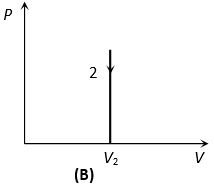
(2) Indicator diagram: Graph 1 and 2 represent isometric increase in pressure at volume and isometric decrease in pressure at volume respectively and slope of indicator diagram
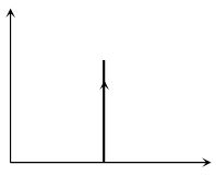
(i) Isometric heating
(a) Pressure increases
(b) Temperature increases
(c) ΔQ positive
(d) ΔU positive
(ii) Isometric cooling
(a) Pressure decreases
(b) Temperature decreases
(c) ΔQ negative
(d) ΔU negative
(3) Specific heat: Specific heat of gas during isochoric process
(4) Bulk modulus of elasticity:
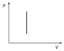
(5) Work done in isochoric process
[As V = constant]
(6) FLOT in isochoric process: From ΔW = ΔU+ΔW
7. ISOTHERMAL PROCESS
When a thermodynamic system undergoes a physical change in such a way that its temperature remains constant, then the change is known as isothermal changes.
Essential condition for isothermal process
(i) The walls of the container must be perfectly conducting to allow free exchange of heat between the gas and its surrounding.
(ii) The process of compression or expansion should be so slow so as to provide time for the exchange of heat. Since these two conditions are not fully realised in practice, therefore, no process is perfectly isothermal.
Equation of state
In this process, P and V change but T = constant i.e. change in temperature T = 0. Boyle’s law is obeyed i.e. PV= constant
P1V1 = P2V2
Example of isothermal process
Melting of ice (at 0°C) and boiling of water (at 100°C) are common example of this process.
Indicator diagram
According to PV = constant, graph between P and V is a part of rectangular hyperbola. The graphs at different temperature are parallel to each other are called isotherms.
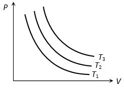
T1<T2< T3
Two isotherms never intersect
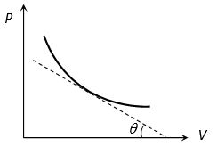
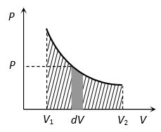
(i) Slope of isothermal curve: By differentiating PV = constant. We get
(ii) Area between the isotherm and volume axis represents the work done in isothermal process. If volume increases ΔW = + (Area under curve) and if volume decreases ΔW = – (Area under curve)
Specific heat Specific heat of gas during isothermal change is infinite. As [As ΔT = 0]
Isothermal elasticity (Eθ)
For this process PV = constant.
i.e. isothermal elasticity is equal to pressure
At N.T.P., Eθ = Atmospheric pressure =
Work done in isothermal process
[As PV = RT]
or
FLOT in isothermal process
From ΔQ = ΔU + ΔW
[As ΔT = 0] ΔQ = ΔW
i.e. heat supplied in an isothermal change is used to do work against external surrounding. or if the work is done on the system than equal amount of heat energy will be liberated by the system.
8. ADIABATIC PROCESS
When a thermodynamic system undergoes a change in such a way that no exchange of heat takes place between System and surroundings, the process is known as adiabatic process. In this process P, V and T changes but ΔQ = 0.
Essential conditions for adiabatic process
(i) There should not be any exchange of heat between the system and its surroundings. All walls of the container and the piston must be perfectly insulating.
(ii) The system should be compressed or allowed to expand suddenly so that there is no time for the exchange of heat between the system and its surroundings.
Since, these two conditions are not fully realised in practice, so no process is perfectly adiabatic.
Some examples of adiabatic process
(i) Sudden compression or expansion of a gas in a container with perfectly non-conducting walls.
(ii) Sudden bursting of the tube of bicycle tyre.
(iii) Propagation of sound waves in air and other gases.
(iv) Expansion of steam in the cylinder of steam engine.
FLOT in adiabatic process:
From ΔQ = ΔU + ΔW
For adiabatic process
If ΔW = positive then ΔU = negative so temperature decreases i.e. adiabatic expansion produce cooling.
If ΔW = negative then ΔU = positive so temperature increases i.e. adiabatic compression produce heating.
Equation of state: In adiabatic change ideal gases do not obeys Boyle’s law but obeys Poisson’s law. According to it
PVγ = constant; where
(i) For temperature and volume
TVγ – 1 = constant
or
(ii) For temperature and pressure
= const.
or
Special cases of adiabatic process
| Type of gas | |||
| Monoatomic γ = 5/3 | |||
| Diatomic γ = 7/5 | |||
| Polyatomic γ = 4/3 |
Indicator diagram
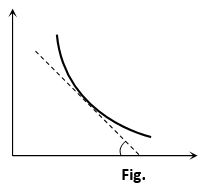
(i) Curve obtained on PV graph are called adiabatic curve.
(ii) Slope of adiabatic curve: From PVγ = constant
By differentiating, we get
Slope of adiabatic curve
(iii) But we also know that slope of isothermal curve
Hence (Slope)Adi = γ⨯(Slope)Iso or
Specific heat
Specific heat of a gas during adiabatic change is zero As [As Q = 0]
Adiabatic elasticity (E)
PVγ = constant
Differentiating both sides
i.e. adiabatic elasticity is γ times that of pressure
Also isothermal elasticity
i.e. the ratio of two elasticity of gases is equal to the ratio of two specific heats.
Work done in adiabatic process
(As PVγ = K, PfVf = RTf and PiVi = RTi)
(i) W quantity of gas (either M or )
(ii) W temperature difference (Ti – Tf)
(iii)
Wmono < Wdia < Wtri
Comparison between isothermal and adiabatic indicator diagrams: Always remember that adiabatic curves are more steeper than isothermal curves
(i) Equal expansion: Graph 1 represent isothermal process and 2 represent adiabatic process
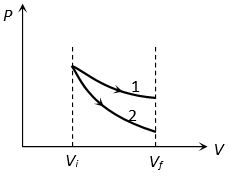
Wisothermal > Wadiabatic
Pisothermal > Padiabatic
Tisothermal > Tadiabatic
(Slope)Isothermal < (Slope)Adiabatic
(ii) Compression: Graph 1 represent adiabatic process and 2 represent isothermal process

WAdiabatic > WIsothermal
PAdiabatic > PIsothermal
TAdiabatic > TIsothermal
(Slope)Isothermal < (Slope)Adiabatic
(10) Free expansion: Free expansion is adiabatic process in which no work is performed on or by the system. Consider two vessels placed in a system which is enclosed with thermal insulation (asbestos-covered). One vessel contains a gas and the other is evacuated. When suddenly the stopcock is opened, the gas rushes into the evacuated vessel and expands freely.
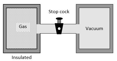
ΔW = 0 (Because walls are rigid)
ΔQ = 0 (Because walls are insulated)
ΔU = Uf – Ui = 0 (Because ΔQ and ΔW are zero. Thus the final and initial energies are equal in free expansion.
9. CYCLIC AND NON-CYCLIC PROCESS
A cyclic process consists of a series of changes which return the system back to its initial state.
In non-cyclic process the series of changes involved do not return the system back to its initial state.
(1) In case of cyclic process as
i.e. change in internal energy for cyclic process is zero and also i.e. temperature of system remains constant.
(2) From FLOT
i.e. heat supplied is equal to the work done by the system.
(3) For cyclic process P-V graph is a closed curve and area enclosed by the closed path represents the work done. If the cycle is clockwise work done is positive and if the cycle is anticlockwise work done is negative.
(4) Work done in non cyclic process depends upon the path chosen or the series of changes involved and can be calculated by the area covered between the curve and volume axis on PV diagram.
10. QUASI STATIC PROCESS
When we perform a process on a given system, its state is, in general, changed. Suppose the initial state of the system is described by the values and the final state by . If the process is performed in such a way that at any instant during the process, the system is very nearly in thermodynamic equilibrium, the process is called quasi-static. This means, we can specify the parameters P, V, T uniquely at any instant during such a process.
Actual processes are not quasi-static. To change the pressure of a gas, we can move a piston inside the enclosure. The gas near the piston is acted upon by piston. The pressure of the gas may not be uniform everywhere while the piston is moving. However, we can move the piston very slowly to make the process as close to quasi-static as we wish. Thus, a quasi-static process is an idealised process in which all changes take place infinitely slowly.
11. REVERSIBLE AND IRREVERSIBLE PROCESS
Reversible process
A reversible process is one which can be reversed in such a way that all changes occurring in the direct process are exactly repeated in the opposite order and inverse sense and no change is left in any of the bodies taking part in the process or in the surroundings. For example if heat is absorbed in the direct process, the same amount of heat should be given out in the reverse process, if work is done on the working substance in the direct process then the same amount of work should be done by the working substance in the reverse process. The conditions for reversibility are
(i) There must be complete absence of dissipative forces such as friction, viscosity, electric resistance etc.
(ii) The direct and reverse processes must take place infinitely slowly.
(iii) The temperature of the system must not differ appreciably from its surroundings.
Some examples of reversible process are
(a) All isothermal and adiabatic changes are reversible if they are performed very slowly.
(b) When a certain amount of heat is absorbed by ice, it melts. If the same amount of heat is removed from it, the water formed in the direct process will be converted into ice.
(c) An extremely slow extension or contraction of a spring without setting up oscillations.
(d) When a perfectly elastic ball falls from some height on a perfectly elastic horizontal plane, the ball rises to the initial height.
(e) If the resistance of a thermocouple is negligible there will be no heat produced due to Joule’s heating effect. In such a case heating or cooling is reversible. At a junction where a cooling effect is produced due to Peltier effect when current flows in one direction and equal heating effect is produced when the current is reversed.
(f) Very slow evaporation or condensation.
It should be remembered that the conditions mentioned for a reversible process can never be realised in practice. Hence, a reversible process is only an ideal concept. In actual process, there is always loss of heat due to friction, conduction, radiation etc.
Irreversible process
Any process which is not reversible exactly is an irreversible process. All natural processes such as conduction, radiation, radioactive decay etc. are irreversible. All practical processes such as free expansion, Joule-Thomson expansion, electrical heating of a wire are also irreversible. Some examples of irreversible processes are given below
(i) When a steel ball is allowed to fall on an inelastic lead sheet, its kinetic energy changes into heat energy by friction. The heat energy raises the temperature of lead sheet. No reverse transformation of heat energy occurs.
(ii) The sudden and fast stretching of a spring may produce vibrations in it. Now a part of the energy is dissipated. This is the case of irreversible process.
(iii) Sudden expansion or contraction and rapid evaporation or condensation are examples of irreversible processes.
(iv) Produced by the passage of an electric current through a resistance is irreversible.
(v) Heat transfer between bodies at different temperatures is also irreversible.
(vi) Joule-Thomson effect is irreversible because on reversing the flow of gas a similar cooling or heating effect is not observed.
12. MIXED GRAPHICAL REPRESENTATION
(1) PV-graphs
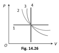
1 Isobaric (P-constant)
2 Isothermal (Because )
3 Adiabatic (Because )
4 Isochoric (V-constant)
(2) PT-graphs
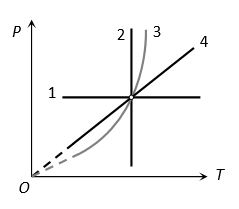
1 Isobaric (P-constant)
2 Isothermal (T-constant)
3 Adiabatic (Because )
4 Isochoric (In isochoric P T)
(3) VT-graphs
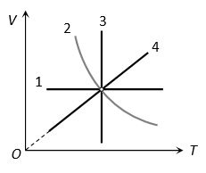
1 Isochoric (V-constant)
2 Adiabatic (Because )
3 Isothermal (T-constant)
4 Isobaric (In isobaric V T )
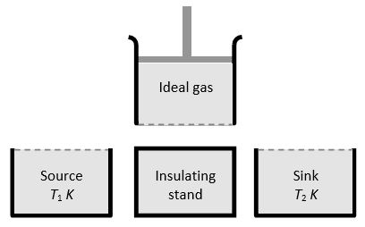
13. HEAT ENGINE
Heat engine is a device which converts heat into work continuously through a cyclic process. The essential parts of a heat engine are
(1) Source: It is a reservoir of heat at high temperature and infinite thermal capacity. Any amount of heat can be extracted from it.
(2) Working substance: Steam, petrol etc.
(3) Sink: It is a reservoir of heat at low temperature and infinite thermal capacity. Any amount of heat can be given to the sink.
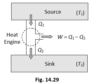
The working substance absorbs heat Q1 from the source, does an amount of work W, returns the remaining amount of heat to the sink and comes back to its original state and there occurs no change in its internal energy.
By repeating the same cycle over and over again, work is continuously obtained.
The performance of heat engine is expressed by means of “efficiency” which is defined as the ratio of useful work obtained from the engine to the heat supplied to it.
For cyclic process ΔU = 0 hence from FLOT ΔQ = ΔW
So
A perfect heat engine is one which converts all heat into work i.e. so that and hence . But practically efficiency of an engine is always less than 1.
14. REFRIGERATOR OR HEAT PUMP
A refrigerator or heat pump is basically a heat engine run in reverse direction.
It essentially consists of three parts
(1) Source: At higher temperature T1.
(2) Working substance: It is called refrigerant liquid ammonia and freon works as a working substance.
(3) Sink: At lower temperature T2.
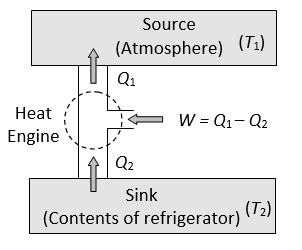
The working substance takes heat Q2 from a sink (contents of refrigerator) at lower temperature, has a net amount of work done W on it by an external agent (usually compressor of refrigerator) and gives out a larger amount of heat Q1 to a hot body at temperature T1 (usually atmosphere). Thus, it transfers heat from a cold to a hot body at the expense of mechanical energy supplied to it by an external agent. The cold body is thus cooled more and more.
The performance of a refrigerator is expressed by means of “coefficient of performance” β which is defined as the ratio of the heat extracted from the cold body to the work needed to transfer it to the hot body.
i.e.
A perfect refrigerator is one which transfers heat from cold to hot body without doing work i.e. W = 0 so that and hence
(1) Carnot refrigerator: For Carnot refrigerator
So coefficient of performance
where T1 = temperature of surrounding, T2 = temperature of cold body. It is clear that β = 0 when T2 = 0 i.e. the coefficient of performance will be zero if the cold body is at the temperature equal to absolute zero.
(2) Relation between coefficient of performance and efficiency of refrigerator
We know ….. (i)
But the efficiency
or …..(ii)
From (i) and (ii) we get,
15. SECOND LAW OF THERMODYNAMICS
First law of thermodynamics merely explains the equivalence of work and heat. It does not explain why heat flows from bodies at higher temperatures to those at lower temperatures. It cannot tell us why the converse is possible. It cannot explain why the efficiency of a heat engine is always less than unity. It is also unable to explain why cool water on stirring gets hotter whereas there is no such effect on stirring warm water in a beaker. Second law of thermodynamics provides answers to these questions. Statement of this law is as follows
Clausius statement
It is impossible for a self acting machine to transfer heat from a colder body to a hotter one without the aid of an external agency.
From Clausius statement it is clear that heat cannot flow from a body at low temperature to one at higher temperature unless work is done by an external agency. This statement is in fair agreement with our experiences in different branches of physics. For example, electrical current cannot flow from a conductor at lower electrostatic potential to that at higher potential unless an external work is done. Similarly, a body at a lower gravitational potential level cannot move up to higher level without work done by an external agency.
Kelvin’s statement:
It is impossible for a body or system to perform continuous work by cooling it to a temperature lower than the temperature of the coldest one of its surroundings. A Carnot engine cannot work if the source and sink are at the same temperature because work done by the engine will result into cooling the source and heating the surroundings more and more.
Kelvin-Planck’s statement:
It is impossible to design an engine that extracts heat and fully utilises into work without producing any other effect.
From this statement it is clear that any amount of heat can never be converted completely into work. It is essential for an engine to return some amount of heat to the sink. An engine essentially requires a source as well as sink. The efficiency of an engine is always less than unity because heat cannot be fully converted into work.
16. CARNOT ENGINE
(1) Carnot designed a theoretical engine which is free from all the defects of a practical engine. This engine cannot be realised in actual practice, however, this can be taken as a standard against which the performance of an actual engine can be judged.
It consists of the following parts
(i) A cylinder with perfectly non-conducting walls and a perfectly conducting base containing a perfect gas as working substance and fitted with a non-conducting frictionless piston
(ii) A source of infinite thermal capacity maintained at constant higher temperature T1.
(iii) A sink of infinite thermal capacity maintained at constant lower temperature T2.
(iv) A perfectly non-conducting stand for the cylinder.
(2) Carnot cycle: As the engine works, the working substance of the engine undergoes a cycle known as Carnot cycle. The Carnot cycle consists of the following four strokes
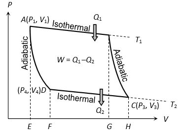
(i) First stroke (Isothermal expansion) (curve AB):
The cylinder containing ideal gas as working substance allowed to expand slowly at this constant temperature T1. Work done = Heat absorbed by the system
Area ABGE
(ii) Second stroke (Adiabatic expansion) (curve BC):
The cylinder is then placed on the non conducting stand and the gas is allowed to expand adiabatically till the temperature falls from T1 to T2.
= Area BCHG
(iii) Third stroke (Isothermal compression) (curve CD):
The cylinder is placed on the sink and the gas is compressed at constant temperature T2. Work done = Heat released by the system
(iv) Fourth stroke (adiabatic compression) (curve DA): Finally the cylinder is again placed on non-conducting stand and the compression is continued so that gas returns to its initial stage.
(3) Efficiency of Carnot cycle: The efficiency of engine is defined as the ratio of work done to the heat supplied
i.e.
Net work done during the complete cycle
or
Since points B and C lie on same adiabatic curve
…..(i)
Also point D and A lie on the same adiabatic curve
…..(ii)
From (i) and (ii),
So efficiency of Carnot engine
(i) Efficiency of a heat engine depends only on temperatures of source and sink and is independent of all other factors.
(ii) All reversible heat engines working between same temperatures are equally efficient and no heat engine can be more efficient than Carnot engine (as it is ideal).
(iii) As on Kelvin scale, temperature can never be negative (as 0 K is defined as the lowest possible temperature) and Tl and T2 are finite, efficiency of a heat engine is always lesser than unity, i.e., whole of heat can never be converted into work which is in accordance with second law.
(4) Carnot theorem: The efficiency of Carnot’s heat engine depends only on the temperature of source (T1) and temperature of sink (T2), i.e., .
Carnot stated that no heat engine working between two given temperatures of source and sink can be more efficient than a perfectly reversible engine (Carnot engine) working between the same two temperatures. Carnot’s reversible engine working between two given temperatures is considered to be the most efficient engine.
Difference Between Petrol Engine and Diesel Engine
| Petrol engine | Diesel engine |
| Working substance is a mixture of petrol vapour and air. | Working substance in this engine is a mixture of diesel vapour and air. |
| Efficiency is smaller (~47%). | Efficiency is larger (~55%). |
| It works with a spark plug. | It works with an oil plug. |
| It is associated with the risk of explosion, because petrol vapour and air is compressed. So, low compression ratio is kept. | No risk of explosion, because only air is compressed. Hence compression ratio is kept large. |
| Petrol vapour and air is created with spark plug. | Spray of diesel is obtained through the jet. |
17. ENTROPY
Entropy is a measure of disorder of molecular motion of a system. Greater is the disorder, greater is the entropy. The change in entropy i.e.
The relation is called the mathematical form of Second Law of Thermodynamics.
(1) For solids and liquids
(i) When heat given to a substance changes its state at constant temperature, then change in entropy where positive sign refers to heat absorption and negative sign to heat evolution.
(ii) When heat given to a substance raises its temperature from T1 to T2, then change in entropy
(2) For a perfect gas: Perfect gas equation for n moles is PV = nRT
[As dQ = dU + dW]
[As PV = RT]
In terms of T and P,
and in terms of P and V
SOLVED EXAMPLES
1. When a system goes from state A to state B, it is supplied with 400J of heat and it does 100J of work.
(i) For this transition, what is the system’s change in internal energy?
(ii) If the system moves from B to A, what is the change in internal energy?
(iii) If in moving from A to B along a different path in which of work is done on the system, how much heat does it absorb?
Sol. (a) From the first law,
(b) Internal energy is a state function, so, is zero for closed path
(c) The change in internal energy is the same for any path
or,
or,
Heat exchanged is =
Negative sign indicates that the system looses heat.
2. A copper block of mass 60g is heated till its temperature is increased by . The heat supplied to the block is 108 calorie. Determine specific heat of copper and heat capacity of copper.
Sol. Heat supplied is
or,
or,
Heat capacity =
3. The molar heat capacity of a gas at constant volume is found to be 5 cal/mol-k. Find the ratio of
Sol. We have,
Thus,
4. A tank of volume contains helium gas at a temperature of 300k and pressure . Find the amount of heat required to raise the temperature of 400k. The molar heat capacity of helium at constant volume is 3.0 cal/mol-k. (No expansion in the volume of tank)
Sol. The amount of the gas in moles is
The amount of heat required is
5. A piece of ice of mass 100g and at temperature is put in 200g of water at . How much ice will melt as the temperature of water reaches ? The specific heat capacity of water and the specific latent heat of fusion of ice .
Sol. The heat released on the water cools down from to is
The amount of ice melted by the much heat is
6. Carnot engine takes in a 100 kcal of heat from reservoir at and exhausts it to a sink at . How much work does it perform? What is the efficiency of the engine?
Sol. Here,
and,
We know that,
Now,
or,
7. Calculate the least amount of work that must be done to freeze one gram of water at by means of refrigerator. How much heat is passed on to the surrounding in this process? (temperature of surrounding is )
Sol. Given that, m = 1 g
and,
Coefficient of performance
or,
Heat passed on to surroundings