


CENTRE OF MASS
1. INTRODUCTION
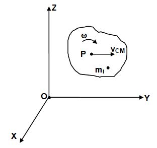
Observations of the motion of bodies indicate that even if a body rotates or these are several bodies that move relative to one another, there is one point that moves in the same path that a particle would if subjected to the same net force. This point is called the centre of mass or centre of inertia. The general motion of an extended body can be considered as the sum of the translational motion of its centre of mass plus rotational, vibrational or other type of motion about its centre of mass.
For an examples, consider the motion of the centre of mass of the diver, the centre of mass follows a parabolic path even when the diver rotates. This is same parabolic path a particle follows when acted on only by the force of gravity (projectile motion other points in the rotating diver’s body follow more complicated paths. Here, we being out study from analysation of centre of mass of different type of objects and it will lead to develop the relation between the Newton’s second law with the concept of conservation of momentum.
Centre of Gravity
A concept similar to centre of mass is centre of gravity. The centre of gravity of a body is that point at which the force of gravity can be consider to act. A conceptual difference between the centre of gravity and the centre of mass, but for practical purposes they are generally the same point.
Centre of Mass
Let us consider a collection of N particles. Let the mass of the ith particle be mi and its coordinates with reference to the chosen axes be xi, yi, zi.
Take the product of mi and xi for each of the particles and add them to get Similarly, we can take and .
Then find,
and
Where, is the total mass of the system.
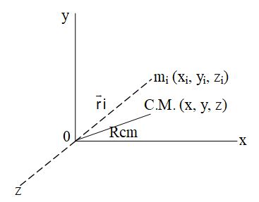
Locate the point with co-ordinates (x, y, z). This point is called the centre of mass of the given collection of the particles. If the position vector of the it particle is , the centre of mass is defined to have the position vector.
Taking x, y and z components of this equation we get the co-ordinates of centre of mass as defined above.
2. CENTRE OF MASS OF DIFFERENT SYSTEMS
I. Centre of mass of two particle
Consider a system of two particles of masses m1 and m2 separated by a distance d. Shown in figure.
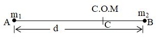
Take the origin at m1 and the x-axis along the line joining m1 and m2. The co-ordinates of m1 are (0, 0, 0) and of m2 are (d, 0, 0)
Therefore,
and,
By definition,
The centre of mass will be at
If A, C, B be the position of m1, the centre of mass and m2 respectively, we have
So that, m1 (AC) = m2 (CB).
The centre of mass divides internally the line joining the two particles in inverse ratio of their masses.
II. Centre of mass of several groups of particles:
Consider the group of N1 particles as the first part and the other group of N2 particles as the second part. Suppose the first part has its centre of mass at C1 and the total mass M1. Similarly the second part has its centre of mass at C2 and the total mass M2.
The x co-ordinate of the centre of mass is
If we know the centre of mass of parts of system and their masses, we can get the combined centre of mass by treating the parts as point particles placed at their respective centre of mass.
III. Continuous Object System
We are required to find the position of the centre of mass of this object, in the given reference frame. For discrete object system we use the relation.
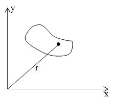
Where, m1, m2 m3 ….. are the component of the system but here in a single non-uniformly shaped object we have infinite components of masses dm each. We can define the position vector of the centre of mass of this body as given by equation.
This relation can also be split into separate x, y and z co-ordinates of the centre of mass of the body as.
and
IV. Characteristics of centre of mass
1. The centre of mass of system of particles depends only on the masses of the particles and their relative positions. For a continuous distributed mass object, it depends on the shape and its mass distribution.
2. Sum of moments of masses of the system about centre of mass is zero, mixi = 0.
3. A mass particle need not be present at the position of the centre of mass. The centre of mass of a uniform ring lies at its centre where we find no mass particle.
4. The location of centre of mass is independent of the reference frame used to locate it.
V. Important Points Regarding Position of Centre of Mass
1. For a 2 dimensional body, the position of COM can be obtained by the formula.
i)
ii)
and
Here A is area of the body.
2. If some mass or area is removed from a rigid body, then the position of COM of the remaining portion is obtained from the formula
i) or
ii) or
or
and or
Here, m1, A1, , x1, y1 and z1 are values for the whole body while m2, A2, , x2, y2 and z2 are the values for the portion which has been removed.
3. CENTRE OF MASS OF DIFFERENT BODIES
I. Centre of mass of uniform straight rod
Let M and L be the mass and the length of the rod respectively. Take the left end of the rod as the origin and the x-axis along the rod. Consider an element of the rod between positions x and x + dx. As the rod is uniform, the mass per unit length is and hence the mass of the element is .
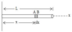
The x-coordinate of the centre of mass of the rod is
The y – co-ordinate in
The centre of mass is
i.e., at the middle point of the rod.
II. Centre of mass of a semicircular Ring
By observation we can say that the x-co-ordinate of the centre of mass of the ring is zero as the half ring is symmetrical on –both sides of the origin. Only we are required to find the y-co-ordinate of the centre of mass.
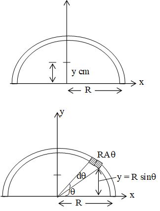
To find, ycm =
Where, dm = mass of the elemental arc. of the ring at an angle θ to θ + dθ. If radius of ring = R, then its y – co-ordinate will be R sinθ.
Then,
III. Centre of mass of a semicircular disc
The mass of half disc is M and radius is R. Again here we are only required to find the y-co-ordinate of the centre of mass of this disc as centre of mass will be located on its half vertical diameter. We consider a small elemental ring of mass dm of radius x on the disc which will be integrated from O to R.
Here
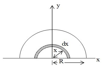
Now, the y-coordinate of dm is taken as , as in previous section, we have derived that mass of a half ring is concentrated at distance from centre.
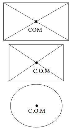
Note: Centre of mass of same well known rigid bodies are given below:
1. Centre of mass of a uniform rectangular, square or circular plate lies at its centre.
2. Centre of mass of a hemispherical shell of Radius R lies at a distance of from its centre on the axis of symmetry as shown in figure.
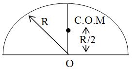
3. Centre of mass of a solid hemisphere of radius R lies at a distance of from its centre on the axis of symmetry.

4. Centre of mass of a hallow cone of radius (base) R lies at a distance of , from its centre at base, where H is the total height of the cone.
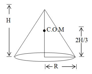
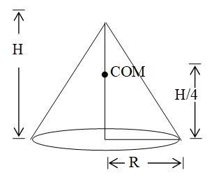
5. Centre of mass of a solid cone of radius (base) R and total height H lies at a distance of from its centre at base.
4. MOTION OF THE CENTRE OF MASS
If the motion of system of n particles of individual masses m1, m2 …. mn and total mass M. It is assumed that no mass enters or leaves the system during its motion, therefore M remains constant.
or,
Differentiating this expression with respect to time t,
or., ….. (1)
Hence, velocity of the COM is
or,
Therefore, = momentum of a particle, =
or, …… (2)
Differentiating equ. (1) w.r.t. time t, we get,
=
or,
using Newton’s law motion, we get,
If no external force applied on the system, =0.
Then,
or,
or, = constant.
This is a case of conservation of momentum.
Hence, the COM of an isolated system has a constant velocity. It implies that, if the COM is at rest, it remains of rest and if the COM is moving with a certain velocity in a certain direction, it continues to move with the same velocity in the same direction, until and unless acted upon by a net external force.
Again, if , then from eq. (13)
or
or . . . . (16)
Where, is the acceleration of COM of the system
or
FORMULAE & CONCEPTS AT A GLANCE
1. Centre of mass of a two particle system lying on a line, say X-axis, is given by
where m1, m2 and the masses of the particles, x1 and x2 are the positions of the masses from a reference point.
2. If the distance between the masses m1,m2 is d ( = d1 + d2), the centre of mass is located in such a way that the distances d1d2 from the particles to the centre of mass are inversely proportional to the masses i.e., .
3. The linear momentum of the centre of mass of a system is the sum of the linear momenta of the particles comprising the system.
M is the mass of the entire system, vc in the velocity of the com of the system, pc in the momentum of centre of mass.
4. Internal forces within the system do not affect the motion of centre of mass.
i.e.,
5. Internal forces within the system do not affect the motion of centre of mass.
ROTATORY MOTION
5. INTRODUCTION TO ROTATIONAL MOTION
So far we have studied the translational motion of single particles or of rigid bodies, that is, of bodies whose all parts have a fixed relationship to each other, irrespective of the force applied. No real body is truly rigid but many bodies e.g. molecules, steel beams, planets, etc., are rigid enough so that the fact that they warp, bend or vibrate can be ignored.
A rigid body moves in translation if each particle of the body undergoes the same displacement as every other particle in any given time interval.
In this chapter, we are interested in rotation. Rotational motion is much more common in nature. The motion of electrons around the nucleus, motion of wheels of the vehicle, mechanism of space crafts or crank shafts of an engine, motion of satellites and planets, all include the concept of rotational mechanics which is the subject matter of this chapter.
Rotational Motion
A rigid body moves in pure rotation if every particle of the body moves in a circle, the centres of which are on a straight line called the ‘axis of rotation’. If we draw perpendicular from any point in the body to the axis, each such line will sweep through the same angle in any given time interval as another such line.
Plane Motion
If the motion of any particle of the rigid body is confined to a plane and planes of motion of different particles are either identical or parallel, the motion of the rigid body is said to be plane motion. During plane motion, the axis of rotation retains its orientation in space.
Examples of plane motion
Note: The general motion of a rigid body is a combination of translation and rotation.
6. UNIFORM ROTATIONAL MOTION
If a body rotates at a constant angular velocity its motion is called uniform rotational motion. If θ be the angular displacement covered by a body under uniform rotational motion in time t, then its angular velocity is given by,
Note: For a body under uniform rotational motion, instantaneous speed at every point of time is equal to its average speed.
Angular Velocity
Angular velocity is the rate of change of angular displacement with time. The S.I. unit of angular velocity is rad and its dimensional formula is .
Angular velocity is a vector quantity and its direction is perpendicular to the plane of rotation of the body. If the body rotates in clockwise direction, the direction of angular velocity is inward the plane and vice- versa.
Instantaneous and Average angular velocity
The angular velocity of a rotating body at a particular instant of time is called instantaneous angular velocity. i.e.
. . . . (1)
The ratio of total angular displacement covered by the body to the total time taken by it to cover this angular displacement is called average angular velocity i.e.
. . . . (2)
Instantaneous and Average Angular Acceleration:
Angular acceleration of a rotating body is defined as the rate at which angular velocity of the body changes. It is represented by .
The S.I. unit of angular acceleration is and its dimensional formula is .
Angular acceleration is also a vector quantity.
Instantaneous angular acceleration is defined as the acceleration of a rotating body at a particular instant of time i.e.
. . . . . (3)
Average value of angular acceleration is the ratio if change in angular velocity to the time taken for this change to take place i.e.
. . . . (4)
Equations of rotational motion
If a body rotates with a constant angular acceleration three simple relations between angular variables are
. . . . (5)
. . . . (6)
and . . . . (7)
Here stands for initial angular velocity of the body.
The three equations stated above are similar to the three equations of kinematics.
7. MOMENT OF INERTIA
According to Newton’s first law of motion, a body is inert to change by itself its position of rest or of uniform motion. This fundamental property of matter is called inertia. It is the mass of the body which is the measure of its inertia for translatory motion.
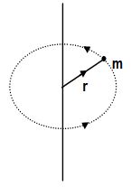
Exactly in the same manner, in the case of rotational motion, a body free to rotate about an axis opposes any change desired to be produced in its state of rest or rotation. Greater is the opposition by the body, the greater is its inertia for rotational motion. It is called its moment of inertia about its axis of rotation. Analytically, for a particle of mass m rotating in a circle of radius r, moment of inertia about the axis of rotation is given by
I = mr2
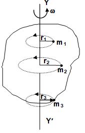
For a discrete distribution of masses m1, m2… etc., at a perpendicular distance r1, r2… etc., respectively from the axis of rotation,
For a continuous distribution of mass, taking an element of mass dm at a distance r from the axis of rotation,
Note
(i) Moment of inertia has dimensions [ML2] and SI unit kgm2.
(ii) It is not a vector as by changing the sense of rotation its value is not changed. It is also not scalar as it has different values in different directions (i.e., about different axes). It is a tensor.*
(iii) It depends on the axis of rotation and for a given axis, depends on mass, shape and size of the body.
(iv) For a given shape, size, mass and axis, it depends on the distribution of mass within the body about the axis. Farther the constituent particles of a body are from the axis of rotation, larger will be its moment of inertia.
(v) Moment of inertia of a part of a rigid body (symmetrically cut from the whole mass) is the same as that of the whole body. For example, in figure (ii) moment of inertia of the section shown (a part of a circular disc) about an axis perpendicular to its plane and passing through point ‘O’ is as, the moment of inertia of the complete disc, figure (i), is also .
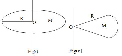
Physical quantities which have no specified direction but different values in different directions are called tensors. Density , refractive index , dielectric constant K, electrical conductivity , stress and strain etc. which are normally scalars, in anisotropic media, assume different values in different directions, so become tensor.
8. THEOREMS ON MOMENT OF INERTIA
Moment of inertia of a system about an axis changes if the position or direction of the axis is changed. If the position of the axis is changed, we use parallel axes theorem and if the direction is changed, perpendicular axes theorem can be used to calculate the moment of inertia.
A. Parallel axes Theorem
Statement:
The moment of inertia of any distribution of matter about an arbitrary axis, I is equal to the moment of inertia of the distribution about an axis passing through its centre of mass and parallel to the arbitrary axis ICM plus Md2 where M is the mass of the distribution and d is the perpendicular distance between the two axes i.e.,
I = ICM + Md2
Proof:

Let us consider a plane lamina of mass M having its centre of mass at G as shown in the figure. Let the lamina be consisting of several small particles each of mass ‘m’ and let us consider a particle at P among them. Assume that this particle is at a distance OP = r from the axis of rotation AB. Further, assume that this particle is at a distance GP = b from another axis EF which is parallel to AB and passing through the centre of mass G. Let the distance between the two parallel axes be ‘x’.
The moment of inertia of the particle at P about the axis AB = m (OP)2 = mr2.
The moment of inertia of the lamina about this axis
Moment of inertia of lamina about the axis EF, passing through the centre of mass G is
From ,
From ,
or,
The body is balanced with respect to the centre of mass G. Hence, the algebraic sum of moments of weights of all particles about G is zero i.e.,
As, the acceleration due to gravity g is constant,
Note: Though the theorem is proved taking the case of a plane lamina, it is applicable to all the rigid bodies.
B. Perpendicular Axes Theorem:
Statement:
The sum of moments of inertia of a plane lamina about two mutually perpendicular axes lying in its plane is equal to its moment of inertia about an axis perpendicular to the plane of lamina and passing through the point of intersection of the first two axes, i.e.,
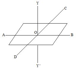
Proof:
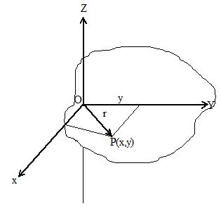
Let us consider a plane lamina of mass M and an axis OZ intersecting the plane of the lamina at O perpendicularly. OX and OY are two mutually perpendicular axes in the plane of the lamina. Assume that the lamina consists of several small particles, each of mass ‘m’. Consider a particle P with coordinates (x, y) at a distance ‘r’ from O.
The moment of inertia of the particle P about the axis
Thus, the moment of inertia of the whole lamina about this axis,
But
But moment of inertia of the lamina about the axis OY.
and moment of inertia of the lamina about the axis OX.
Caution: Parallel axes theorem is used for all types of bodies (one, two or three dimensional) but perpendicular axes theorem is used only for two dimensional bodies only.
9. MOMENT OF INERTIA OF DIFFERENT BODIES
Thin uniform rod:
Consider a thin uniform rod of mass M and length l. We have to calculate moment of inertia of the rod about an axis passing through the centre O of the rod and perpendicular to its length.
Now, Mass per unit length of rod =
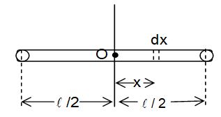
Consider a small element of length dx, of the rod at a distance x from the centre.
Mass of this element =
Moment of inertia of this element about the given axis.
As this element can lie anywhere from left end of the rod to its right end i.e. from
Moment of inertia of the rod,
or . . . . (15)
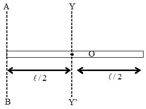
II. Rectangular Lamina
Moment of inertia of a rectangular lamina about a line parallel to an edge and passing through the centre
Let us consider a rectangular lamina of mass M and length l and breadth b. YY’ is an axis parallel to the breadth and passing through the centre. Let us consider a strip of width dx at a perpendicular distance x from the axis. As the lamina is uniform its mass per unit area =
Mass of the strip = .
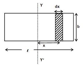
The moment of inertia of the strip about YY’
Thus, the moment of inertia of the given lamina is
Similarly, we can obtain the moment of inertia of the lamina about the axis parallel to the other edge (i.e., the length) and passing through the centre as
III. Circular Ring
Moment of inertia of a circular ring about its axis (the line perpendicular to the plane of the ring and passing through its centre):

Let us consider a thin ring of mass M and radius R. As all the elements of the ring are at the same perpendicular distance R form the axis YY’, the moment of the inertia of the ring is
IV. Uniform Circular Disc
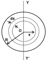
Moment of inertia of a uniform circular disc about its axis

Let M be the mass of the disc and R be its radius. O is the centre of the disc and YY’ its axis, i.e, the axis through its centre and perpendicular to its plane.
Mass per unit area =
Let us consider a ring of radius x centred at O and thickness dx. Mass of this ring is
Moment of inertia of the ring about the axis
dI = dmx2
Moment of inertia of the whole disc
V. Hollow Cylinder
Moment of inertia of a hollow cylinder about its axis
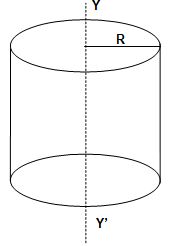
Let us consider a hollow cylinder of mass M and radius R. As every element of this cylinder is at the same perpendicular distance R form its axis YY’, the moment of inertia of the cylinder about the axis is
VI. Uniform Solid Cylinder
Moment of inertia of a uniform solid cylinder about its axis
Consider a uniform solid cylinder of mass M, radius R, and length l.
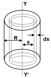
Mass per unit volume (i.e., density) of the cylinder,
Let us consider a coaxial hollow cylinder of radius x and thickness dx.
The mass of this hollow cylinder,
Moment of inertia of the hollow cylinder about its axis YY’
Thus, the moment of inertia of the cylinder is
Note: The moment of inertia does not depend on the length of the cylinder.
VII. Uniform hollow sphere
Moment of inertia of a uniform hollow sphere about an axis passing through its centre
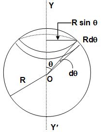
Let M and R be the mass and the radius of a uniform hollow sphere of negligible thickness, O its centre and YY’ the given axis passing through the centre.
Mass per unit area of the sphere =
Let us consider a ring of radius Rsinθ and thickness Rdθ as shown in the figure.
The mass of the ring
The moment of inertia of the hollow sphere is
VIII. Uniform Solid Sphere
Moment of inertia of a uniform solid sphere about an axis passing through its centre:
Let M and R be the mass and the radius of a uniform solid sphere, O its centre and YY’ the given axis passing through the centre.
The mass per unit volume i.e., density of the sphere
Let us consider a concentric spherical shell of radius x and thickness dx. The mass of the shell
The moment of inertia of the shell about the axis YY’
The moment of inertia of the solid sphere about YY’ is
Applications
1. Moment of inertia of a thin uniform rod about an axis passing through its one end and perpendicular to its length:
Let us consider a thin uniform rod of mass M and length l. Let YY’ be an axis passing through the centre of the rod and perpendicular to its length. Let AB be an axis parallel to YY’ and passing through one of its ends. The moment of inertia of the rod about YY’,
Thus, by parallel axes theorem, moment of inertia of the rod about AB,
2. Moment of inertia of a circular disc about an axis passing through any of its diameters:
Let us consider a circular disc of mass M and radius R.
The moment of inertia of the disc about an axis passing through its centre and perpendicular to its plane (YY’) is
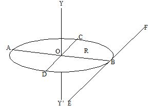
Let Id be its moment of inertia about an axis passing through any of its diameters. If AB and CD be two mutually perpendicular diameters, then according to the perpendicular axes theorem,
or, or,
The moment of inertia of the disc about a tangent in its plane can be derived using parallel axes theorem as
3. Moment of inertia of a rectangular lamina about an axis passing through its centre and perpendicular to its plane:
Let us consider a rectangular lamina of mass ‘m’, length ‘l’ and breadth ‘b’. AB and CD are two axes passing through the centre of the lamina, O and parallel to its length and breadth respectively. Then
If YY’ be the axis passing through O and perpendicular to the lamina, by perpendicular axes theorem,
Moments of inertia of some regular bodies
| Body | Reference Axis | Moment of Inertia |
| Circular ring of radius R and mass M | i) axis through its centre and perpendicular to its plane | |
| ii) any diameter | ||
| A thin circular disc of radius R and mass M | i) passing through the centre of mass and perpendicular to the plane of the disc | |
| ii) diameter of the disc | ||
| Hollow cylinder of radius R and mass M (tube) | i) its own axis | |
| Solid cylinder of radius R, mass M and length | i) axis of the cylinder | |
| ii) perpendicular to the axis of the cylinder and passing through its centre | ||
| iii) diameter of the cross section | ||
| Hollow sphere of mass M and radius R | i) diameter | |
| ii) tangent to the surface | ||
| Solid sphere of mass M and radius R | i) diameter | |
| ii) tangent to the surface | ||
| Rectangular lamina of mass M, length and breadth b. | i) passing through the centre and parallel to its length | |
| ii) passing through the centre and parallel to its breadth | ||
| iii) passing through the centre and perpendicular to its plane |
Radius of gyration
The radial distance from a given axis at which the mass of a body could be concentrated without altering the rotational inertia of the body about the axis is called the radius of gyration. If k is the radius of gyration of a body of mass m and moment of inertia I about a given axis,
Note:
We know for a system of ‘n’ particles each of equal mass ‘m’ and at distances from the axis of rotation, the moment of inertia.
If M = mn = total mass of the system,
where
Hence, the radius of gyration of a body about an axis is also defined as the root-mean-square distance of the particles of the body from the axis of rotation.
ROTATIONAL DYNAMICS
Torque
It is the force which changes the state of translatory motion. Torque plays the same role in rotational motion i.e. it is the rotational analogue of the force. It is the turning action of the force about a given point. The torque of a force acting on a particle P about a given point O is defined as where is the position vector of the point of application P of force relative to the point O.
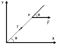
Thus, where θ is the angle between and , and is the unit vector perpendicular to the plane containing and .
Note:
(i) Torque is an axial vector.
(ii) It has dimension [ML2T–2], same as that of work or energy.
Caution: Though dimensionally, torque is same as work or energy, its unit is Nm, not Joule.
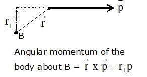
(iii) It is also called as moment of force. As
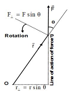
where = perpendicular component of the position vector , called the moment arm, and = F sin = perpendicular component of the force .
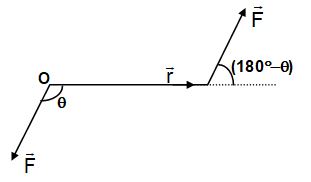
(iv) It is conventional to take the torque positive if the body rotates anticlockwise as viewed through the axis, and negative otherwise.
(v) For a system of n particles the total torque
where, is the position vector of the ith particle and is the force acting on the ith particle.
Caution: For such a system, the torque about the axis is, in general, not equal to the torque of the resultant force. Even if , may not be zero. However, if the forces act on the same particle,
(vi) A body is said to be in rotational equilibrium if resultant torque acting on it is zero i.e.,.
As for translatory equilibrium, , for the equilibrium of a body or system, the two conditions must be satisfied independently:
Couple
A couple is defined as the combination of two equal but oppositely directed forces not acting along the same line.
The torque exerted by a couple is given by
and is independent of the location of the axis of rotation. As the net force on the body is zero, it is in translatory equilibrium but not in rotatory equilibrium.
Torque on a rigid body
Consider a rigid body rotating about a fixed axis YY’. Consider a particle P of mass m rotating in a circle of radius r.
The radial force on the particle P = m2r
The torque of the radial force about YY’ is zero as it intersects the axis.
The tangential force on the particle = .
The torque of mr is mr2 as the force and the axis are skew and perpendicular.
Thus, the net torque on the particle P,
The total torque of all the forces acting on all the particles of the body
The quantity I is called the moment of inertia of the body about the axis of rotation. mi is the mass of the ith particle and ri is its perpendicular distance from the axis.
Also, , where is the resultant force on the ith particle.
Now, ,
where = force on the ith particle due to the jth particle, and
= external force applied on the ith particle.
Two nonparallel and non-intersecting lines are called skew lines.
When summation is made on both i and j, the first summation contains pairs like . As according to the Newton’s third law. So such pairs become . Now,
= Torque due to external forces.
Thus, we conclude that ,
where the torque and the moment of inertia are both evaluated about the axis of rotation.
13. ANGULAR MOMENTUM & IMPULSE
Angular momentum
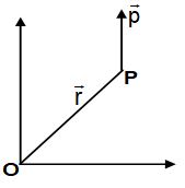
Angular momentum of a particle about a given point O is defined as
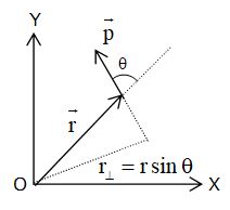
where = linear momentum of the particle = position vector of the particle with respect to the given point O.
θ = angle between and , and = unit vector perpendicular to the plane containing and .
Note:
(i) Angular momentum is an axial vector (i.e., always perpendicular to the plane of motion) having dimension [ML2T–1] and SI unit J-s (same as that of Planck’s constant).
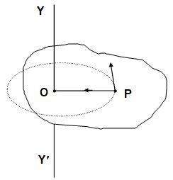
(ii) As torque is defined as the moment of force, angular momentum is also referred as moment of linear momentum. The perpendicular distance of the linear momentum from the given point is called the moment arm.
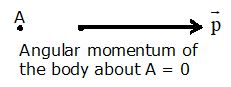
(iii) A body which translates can also have angular momentum about a point unless the point is on the line of motion.
(iv) In case of circular motion of a particle, the angular momentum about the centre of the circle
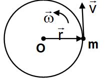
= mvr
=
=
(v) As in the case of torque, we define the angular momentum of a particle about an axis, say YY’. It is the component of the angular momentum of the particle about any point O on the axis (= ) along the axis YY’. It is independent of the choice of the point O on the given axis.

Angular momentum of a rigid body in a fixed axis of rotation:
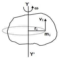
Consider a rigid body rotating about an axis YY’. Let the angular velocity of the body be . So each particle will be moving in a circle with its plane perpendicular to YY’. If the ith particle of mass mi is moving in a circle of radius ri , the angular momentum of the particle about YY’.
.
The angular momentum of the whole body about YY’,
where I = moment of inertia of the body about YY’.
Caution: The vector always points along the axis of rotation of spinning body but, in general, the vector does not. Only for bodies with symmetry about the rotational axis, both and point along the axis, assuming that the axis is fixed or, the axis passes through the centre of the mass and the moving axis always has the same direction in space. However, the vector component of along the rotational axis is equal to I for any rigid body, symmetrical or not.
Angular momentum of a rigid body describing general plane motion
If the planes of motion of any two particle of a rigid body are either identical or do not intersect at all (i.e. are parallel), the motion of the rigid body is said to be in a plane. During the plane motion, the axis of motion retains its orientation in space.
Let us consider a rigid body moving in a plane with its centre of mass P moving with velocity , and the body rotating about an axis passing through its centre of mass and perpendicular to the plane of motion.
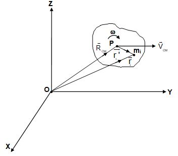
Let us consider the particle of mass mi of the rigid body.
Then, = position vector of mi relative to centre of mass.
where = velocity vector of mi relative to centre of mass.
Angular momentum of the rigid body about the origin O is
=
where angular momentum of the body about point O,
= angular momentum of the body about the centre of mass, and () = angular momentum of the centre of mass about the point O.
Thus, we can separate the general motion of a rigid body into the translational motion of its centre of mass and rotational motion about its centre of mass.
Relation between angular momentum and torque about any point for a particle:
Angular momentum of a particle P about any point O is given by
where = position vector of the particle P and momentum of the particle.
Differentiating with respect to time, we get
Thus, the time rate of change angular momentum of a particle relative to a point O is equal to the net torque acting on the particle about the point O.
Caution: The above equation is derived considering the point O fixed in a inertial reference frame. If the point O is accelerating (i.e. non-inertial), the net torque in the equation must include the torque due to pseudo forces about point O.
Relation between angular momentum and torque for a system of particles (rigid body)
The angular momentum of a body is given as the vector sum of the angular momenta of all the constituent particles, i.e.,
Here is the total force acting on the ith particle which includes the external force as well as the internal forces on the ith particle by all the other particles. When summation is taken over all the particles, the torques due to internal forces add to zero, as shown on page no. 112.
Thus,
where is the total torque on the system due to all the external forces acting on the system.
Caution: In an accelerating frame of reference, the net external torque must include the torque of pseudo forces acting on the centre of the mass of the system. But if the and are measured with respect to the centre of mass of the body, the torque due to pseudo forces will be zero and thus represents the torque of only real external forces even in non-inertial frame of reference.
Law of Conservation of Angular Momentum:
For a system of particles (or a rigid body) we have
If then =0
so that = constant.
Thus, when the resultant external torque acting on a system is zero, the angular momentum of the system remains constant. This is the principle of conservation of angular momentum.
Note:
(i) For a system of n particles, total angular momentum
Hence, when the external torque is zero,
= constant.
This shows that angular momentum of individual particles may change, but their sum remains constant in the absence of an external torque.
(ii) For a single body rotating about a fixed axis
L = I
Now, if no external torque is applied
L = I = constant
So, if I is changed by changing the distribution of mass with respect to the axis of rotation, will also change so that I remains constant.
Examples:
1. Let us assume that a person is standing on a turn table rotating about a vertical axis, and is holding a pair of weights. When the person suddenly folds his arms, the moment of inertia of the system decreases as the radius of gyration decreases. Since no external torque acts on the system, the angular velocity of the system increases.
2. A driver performs somersaults by jumping form a high diving board keeping his legs and arms stretched out first, and then curling his body. On doing so, moment of inertia of his body decreases and hence, its angular velocity increases.
3. If a flywheel fixed in space-ship rotates in clockwise direction, according to the law of conservation of angular momentum, the space-ship moves in anticlockwise direction.
14. KINETIC ENERGY
If a large torque acts on a particle for a small time dt then angular impulse of the torque in a given time interval is defined as
= Change in angular momentum
Also, angular impulse = moment of linear impulse
i.e., , where = linear impulse = .
Kinetic Energy of a Rigid Body in a Fixed Axis Rotation
Consider a rigid body rotating about the axis YY’ with an angular speed . The ith particle of mass mi is going in a circle of radius ri with a linear speed . Thus, the kinetic energy of the particle = =
Thus, the rotational kinetic energy of the whole body is
Power Delivered and Work Done by a Torque
According to the work energy theorem,
W = K
Thus, the power delivered by the torque
=
Also, the work done in an infinitesimal angular displacement dθ is
dW = Pdt = dt = dθ
The work done in a finite angular displacement θ1 to θ2 is
Total Kinetic Energy of a Rigid Body in Plane Motion:
Let us consider a rigid body moving in a plane. The velocity of its centre of mass P is .
The body also rotates about an axis passing through P and perpendicular to the plane of motion.
The velocity of the ith particle relative to the origin O is
= velocity of the particle with respect to the centre of mass.
The kinetic energy of the body
Now, , where = position vector of the ith particle relative to the centre of mass.
where I = moment of inertia of the body about the axis passing through the centre of mass.
Thus, the total kinetic energy in a plane motion is the sum of translational kinetic energy of the centre of mass and the rotational kinetic energy of the body about its centre of mass
15. ROLLING MOTION
A rigid body in plane motion
We have seen that the plane motion of a rigid body is a combination of rotational motion about a fixed axis and the translatory motion of the axis of rotation. Also, if the axis of rotation passes through the centre of mass of the body, the torque of the pseudo force in a non-inertial frame about the axis is zero. Thus, the force and torque equation for the rigid body becomes
and .
Rolling Motion
In case of combined translatory and rotatory motion, if the object rolls across a surface in such a way that there is no relative motion between the object and the surface at the point of contact, the motion is called pure rolling. If there is a relative motion between the object and the surface, it is rolling with slipping.
Consider a uniform sphere with centre of mass C rolling on a rough plank as shown in the figure. Let P and P’ be the points of contact of the sphere and the plank respectively. For pure rolling,

If the surface is stationary,
For pure rolling v = R
Also, for pure rolling
If the planck is stationary, a0 = 0, for pure rolling
a = R
If or the motion is said to be rolling with forward slipping.
If or the motion is said to be rolling with backward slipping.
Direction of Frictional Force on a Rigid Body Rolling on a Stationary Rough Horizontal Surface
Suppose a force F is applied at a height h above the centre of mass O of a body of mass m and radius R. The moment of inertia of the body about O is ICM. Assume that the frictional force acts in the forward direction i.e., same as the direction of . Acceleration of the centre of mass of the body,
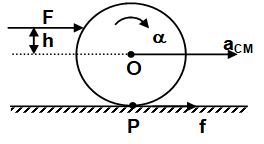
Angular acceleration of the body
For pure rolling,
Case I: If
f = 0
The point of contact remains stationary and the motion is pure rolling.
Case II:
f > 0 i.e., friction is in the forward direction
The point of contact has a tendency to slip in backward direction (a < R) and hence f will act in forward direction to provide pure rolling.
Case III:
f < 0 i.e. friction is in the backward direction.
The point of contact has a tendency to slip in forward direction (a> R) and hence f will act in backward direction to provide pure rolling.
Kinetic energy of a rolling body
As derived earlier, kinetic energy of a body in plane motion,
where, = Kinetic energy of rotation about the centre of mass and = KT = Kinetic energy of translation of the centre of mass.
In case of pure rolling motion,
, where R is the radius of the body.
If k is the radius of gyration of the body,
Now, moment of inertia of the body about the contact point P is
Thus, rolling about the centre of mass O is equivalent to rotation about the point of contact P with the same angular velocity . Thus, point of contact is the instantaneous centre of rotation.
Also, percentage of translational kinetic energy
Similarly, percentage of rotational kinetic energy =
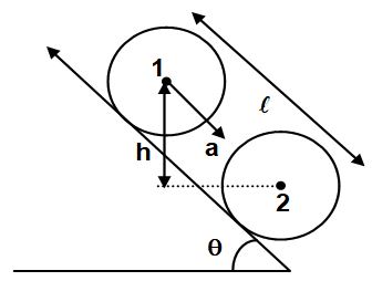
16. ROLLING MOTION ON AN INCLINED PLANE
Force-Torque Method
Consider a rigid body of mass M rolling on a plane inclined at an angle θ with the horizontal. Writing the force and torque equation, we get
…(i)
…(ii)
Also, …(iii)
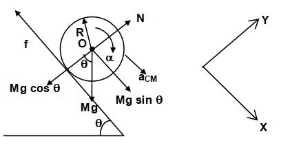
(Torque due to Mg and N is zero as they pass through the centre of mass.)
Here, f = frictional force acting on the body,
ICM = moment of inertia of the body about the centre of mass O.
Now, for pure rolling
…(iv)
[from (iii) and (iv)]
Putting the value of f in (i), we get
If , where k = radius of gyration of the body about its centre of mass, then
Also, minimum friction for pure rolling
The maximum possible value of friction on the body
Thus,
or,
Thus, minimum value of coefficient of friction required for pure rolling,
Energy Method
In pure rolling, contact point is at rest with respect to the surface. Thus, friction does no work. Hence, total mechanical energy is conserved in pure rolling.
Let the rigid body at rest be at position 1 and travels a distance l along the incline upto position 2 in time t.
The velocity of the centre of mass at position 2 is vCM.
Applying conservation of mechanical energy between the two position, we get
As for pure rolling,
Also,
Here, u = 0 and
Analogy between Rotational and Linear Motion
| Translatory Motion | Rotatory Motion |
|
1. Mass of the body, m 2. Linear displacement 3. Linear velocity, 4. Linear acceleration, 5. 6. 7. 8. 9. Linear momentum, 10. Force, 11. Work, 12. Translatory kinetic energy, 13. Power, |
Moment of inertia, I Angular displacement Angular velocity, Angular acceleration, Angular momentum, Torque, Work, Rotatory kinetic energy, Power, P = |
Motion in a vertical circle
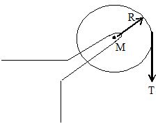
In the air force anniversary functions, we observe with delight the various feats performed by the planes moving in vertical circles in various configurations with case. We will understand in this section how this is possible
A body of mass ‘m’ is tied to one end of a string and whirled rapidly in a vertical plane holding the second end. The motion of the body on the circular path will not be uniform. The body will have difference velocities at different points on the circle. It continues to move on the circular path only when it crosses the lowest point P1 with certain minimum velocity.
Let the tension in the string be T1 and the velocity of the body be v1 when it crosses the lowest point on the circle. This tension acts in the upward direction. Similarly, let the tension in the string be T2, when the body crosses the highest point P2 with a velocity v2. This tension acts in the downward direction.
The forces acting on the body when it is at P1 are
i) Tension ‘T1’ in the upward direction.
ii) Weight ‘mg’ of the body acting in the downward direction.
The net force on the body supplies the necessary centripetal force,
When the body is at P2, tension T2 acts in the downward direction. So,
If T2 = 0
Then
This velocity v2 is called “critical velocity”. If the velocity of the body at the highest point, is less than ,
the string becomes loose and the body falls down without moving along the circumference. The minimum velocity of the body at P1 must be such that its velocity of P will not be less than .
The body attains a height 2R while going from P1 to P2. When it is at P1, its kinetic energy will be only but when it is at P2 it possesses a kinetic energy of and a potential energy of 2mg R. According to the law of conservation of energy.
But we know that
So, for a body to be in vertical circular path its minimum velocity (v1)min at its lowest point must be
Hence, while looping an aircraft in a vertical circular path or driving a motor cycle in a vertical circular path in a circular path must be . Under the same conditions, if some water is taken in a bucket and whirled with the help of a string at a greater velocity in the vertical plane, the water will not spill out from, the bucket even if it is at the highest point of its circular path.
SOLVED EXAMPLES
1. Three particles A, B and C having masses m, 2m and 3m respectively are placed in order at the vertices of a equilateral triangle of side a. Determine the centre of mass.
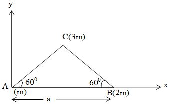
Sol. Take the axes as shown in figure the co-ordinates of the three particles as follows.
| Particle | Mass | x – coordinate | y – coordinate |
| A | m | o | o |
| B | 2m | a | o |
| C | 3m | a cos 600 | a sin 600 |
Hence, the co-ordinates of the centre of mass of the three particle system are,
and
2. Consider a rectangular plate of dimensions a x b. If this plate is considered to be make up of four rectangles of dimensions and we now remove one out of four rectangles. Find the position of the centre of mass of the remaining system.
Sol. The rectangular plate is shown in figure, of which one part is removed. We can find the x and y coordinate of the centre of mass of this system, taking origin at centre of the plate.
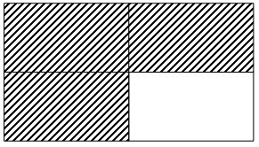
Masses of the three remaining rectangles can be taken an and coordinate of these are .
Now, x – co-ordinate of the centre of mass;
and, y – co-ordinate of centre of mass.
3. A circular disc of radius R from which small disc is cut such that the periphery of the small disc touch large disc and whose radius is R/2. Find the centre of mass of the remaining part of the disc.
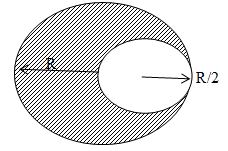
Sol. If masses of the removed disc and the remaining portion are m1 and m2. Let C.M. of the remaining portion be at a distance x from the centre. We have,
and
Now, applying the concept of centre of mass of a two body system, we get the distance x at which the centre of mass of the remaining portion of the disc lie as.
or,
or,
or,
4. The position vector of three particles of mass m1 = 1 kg, m2 = 2kg and m3= 3kg are , and respectively. Find the position vector of their COM.
Sol. We have,
or
or or
5. A rod of length L is placed along the x – axis between x = 0 and x = L. The linear density (mass / length) of the rod varies with the distance x from the origin as = a + bx. Here, a and b are constants. Find the position of centre of mass of this rod.
Sol. Mass of element PQ of length dx situated at n = x is ,
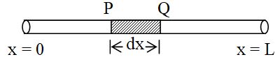
dm = dx = (a + bx ) dx
The centre of mass of the element has co-ordinates (x, 0, 0). Therefore x-co-ordinate of COM of the rod will be
or,
Hence, the centre of mass of the rod lies at
6. A rod of length L is placed along the x – axis between x = 0 and x = L. The linear density (mass / length) of the rod varies with the distance x from the origin as = a + bx. Here, a and b are constants. Find the position of centre of mass of this rod.
Sol. Mass of element PQ of length dx situated at n = x is ,
dm = dx = (a + bx ) dx
The centre of mass of the element has co-ordinates (x, 0, 0). Therefore x-co-ordinate of COM of the rod will be
or,
Hence, the centre of mass of the rod lies at
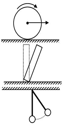
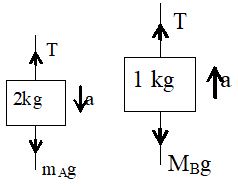
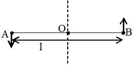
7. In the given figure, mA = 2kg and mB =1 kg. String in light and inextensible. Find the acceleration of centre of mass of both the blocks. Neglect friction everywhere.
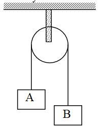
Sol. Free body diagram of block A is shown in figure
2g – T = 2a ….. (1)
and free body diagram of B.
T – 1g = 1a …… (2)
From equation (1) and (2), we get,
Now, acceleration of centre of mass,
downward.
8. The angular displacement of a rotating body varies with time as Find
a) its instantaneous angular velocity at t = 2s
b) its average angular velocity in first 2s.
Sol. a) We have
at t = 2s, rad
b) Given
at t = 0, rad.
And at t= 2s, rad.
9. The angular displacement of a rotating body varies with time as Find
a) its angular acceleration at t = 5s
b) its average angular acceleration between t=2s to t=5s
Sol. Given,
(a)
at t = 5s, 40
(b) As
at t = 2s,
at t = 5s,
10. A flywheel rotating at 420 rpm slows down at a constant rate of 2 rads–2. In how much time will it stop?
Sol. Here, n1=420 rpm =
= -2 rads–2, t = ? n = 0
as
11. Two point masses m1 and m2 are joined by a weightless rod of length ‘l’. Find the moment of inertia of the system about an axis passing through the centre of mass and perpendicular to the rod.
Sol. If l1 and l2 are the distances of the masses m1 and m2 from the centre of mass O, then the moment of inertia of the system about the axis through O i.e, YY’ is
By the definition of centre of mass,
Given,
or,
where and is called the reduced mass of the system.
12. Three rods each of mass ‘m’ and length ‘l’ are joined together to form an equilateral triangle as shown in the figure. Find the moment of inertia of the system about an axis passing through its centre of mass ‘O’ and perpendicular to the plane of the triangle.

Sol. Moment of inertia of the rod BC about an axis perpendicular to the plane of the triangle ABC and passing through its mid-point, Q is
Using theorem of parallel axes, moment of inertia of the rod about a parallel axis through O is
Moment of inertia of the triangle about the axis passing through O is
13. Find out the radius of gyration of the triangle in illustration 7, about the axis passing through O and perpendicular to the plane ABC.
Sol. We have found that the moment of inertia of the triangle ABC about the given axis.
As total mass of the system M = 3m,
Radius of gyration,
14. A uniform cube of size ‘a’ and mass M rests on a rough horizontal table. A horizontal force F is applied normal to one of the vertical faces at a height (3a/4) from the base. What is the minimum value of F for which the cube begins to tip about an edge?
Sol. The cube will tip about the edge through O if torque of F about O exceeds the torque of Mg (Torque of R and frictional force ‘f ’about O is zero.)
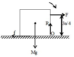
i.e.,
i.e.,
15. A uniform disc of mass M and radius R is mounted on an axle supported in fixed frictionless bearings as shown in the figure. A light cord is wrapped around the rim of the wheel and a steady downward pull T is exerted on the cord. Find
a) the angular acceleration of the wheel, and
b) the tangential acceleration of a point on the rim.
(Moment of inertia of the disc, )
Sol. a) The torque acting on the disc about the central axis
From , we have
or,
where angular acceleration of the disc.
b) The tangential acceleration of a point on the rim is given by
16. Two particles A and B, each of mass ‘m’, are attached rigidly to the ends of a light rod of length ‘l’. The structure rotates about the perpendicular bisector of the rod at an angular speed . Calculate the angular momentum of the individual particles and of the system about the axis of rotation.
Sol. The velocity of the particle A with respect to the centre O is
The angular momentum of the particle A with respect to the axis is
Similarly, the angular momentum of the particle B with respect to the axis is
The angular momentum of the system
(Since and are in same direction.)
The total angular momentum points out of the plane of the paper perpendicularly.
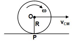
17. A disc of mass M and radius R is rolling with angular speed on a horizontal plane as shown in the figure. Find the magnitude of angular momentum of the disc about the origin O.
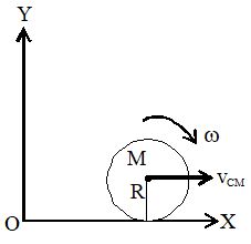
Sol. Linear velocity of the centre of mass of the disc
Angular momentum of the centre of mass with respect to O,
perpendicular to paper inward.
Also, angular momentum of the disc about the centre of mass,
perpendicular to paper inwards.
Thus, the total angular momentum of the body with respect to O
Since points in the same direction,
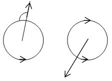
18. A wheel A is rotating at an angular speed about its axis which is kept vertical. Another identical wheel B rotating in the same direction at an angular speed is gently dropped into the same axle and the two wheels start rotating with a common angular speed. Find this common angular speed.
Sol. If the moment of inertia of both the wheels be I, the angular momentum of the system (consisting of both the wheels) before the coupling is
Let the common angular speed of the two wheels after coupling is . The total angular momentum,
Since there is no external torque acting on the system, law of conservation of angular momentum gives
or,
or,
19. A uniform sphere of mass 2kg rolls without slipping on a plane surface so that its centre moves at a speed of 2 m/s. Find its kinetic energy.
Sol. The angular speed of the sphere about the centre,
Thus, the kinetic energy is
.